3.2 Standard Connection Diagram
YASKAWA ELECTRIC SIEP C710616 35D YASKAWA AC Drive E1000 Technical Manual 59
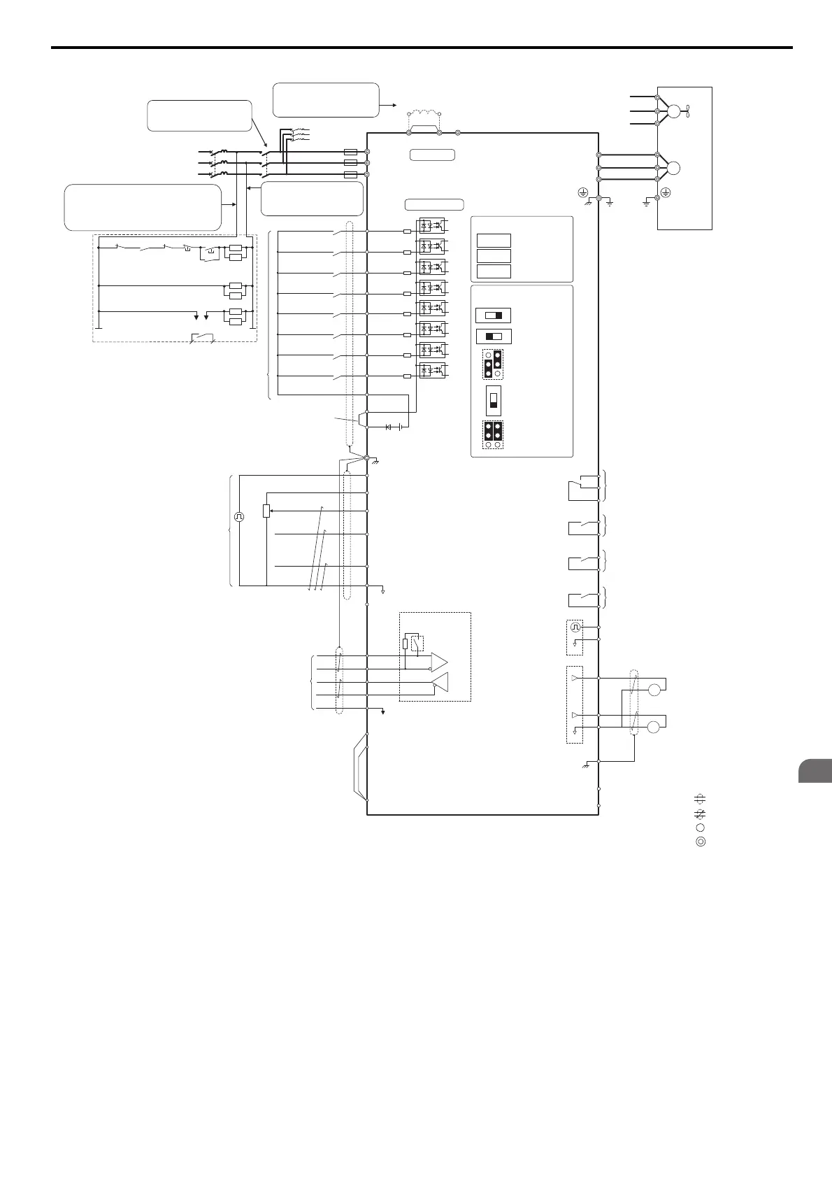
Figure 3.1
Figure 3.1 Drive Standard Connection Diagram (example: CIMR-E2A0040)
<1> Remove the jumper when installing a DC reactor. Models CIMR-E2A0110 through 2A0415 and 4A0058 through 4A1200 come with a
built-in DC reactor.
<2> Self-cooling motors do not require wiring that would be necessary with motors using a cooling fan.
<3> Supplying power to the control circuit separately from the main circuit requires a 24 V power supply (option).
<4> This figure shows an example of a sequence input to S1 through S8 using a non-powered relay or an NPN transistor. Install the wire link
between terminals SC-SP for Sink mode and SC-SN for Source mode. Leave it out for external power supply. Never short terminals SP and
SN as doing so will damage the drive.
<5> The maximum current supplied by this voltage source is 150 mA.
<6> The maximum output current capacity for the +V and -V terminals on the control circuit is 20 mA. Never short terminals +V, -V, and AC, as
this can cause erroneous operation or damage the drive.
<7> Set DIP switch S1 to select between a voltage or current input signal to terminal A2. The default setting is for current input.
<8> Set DIP switch S4 to select between analog or PTC input for terminal A3.
<9> Enable the termination resistor in the last drive in a MEMOBUS network by setting DIP switch S2 to the ON position.
<10> Monitor outputs work with devices such as analog frequency meters, ammeters, voltmeters, and wattmeters. They are not intended for use as
a feedback-type of signal.
Jumper S3
Terminal H1/H2
Sink/Source
Selection
+
+
+
+
+
−
S1
S2
S3
S4
S5
S6
S7
MP
RP
A
1
A2
A3
0
V
AC
R
R
S
S
IG
2 kΩ
S8
SC
0 V
0 V
AC
FM
AM
AC
E (G)
<6>
<10>
<10>
<7>
<9>
<6>
<4>
<4>
+
24 V
+V
MA
M1
M2
MB
MC
Forward Run / Stop
Reverse Run / Stop
External fault
Fault reset
Multi-step speed1
Multi-step speed2
External Baseblock
Jog speed
Multi-function
digtial inputs
(default setting)
Sink / Source mode
selection wire link
(default: Sink)
CN5-A
Option card connectors
Pulse Train Input (max 32 kHz)
Shield ground terminal
Multi-function
analog/ pulse
train inputs
Power supply +10.5 Vdc, max. 20 mA
Analog Input 1 (Frequency Reference Bias)
-10 to +10 Vdc (20 k
Ω
)
Analog Input 2 (Frequency Reference Bias)
-10 to +10 Vdc (20 k
Ω
)
0 or 4 to 20 mA (250
Ω
)
Analog Input 3 / PTC Input (Aux. frequency
reference)
-10 to +10 Vdc (20 k
Ω
)
−V
Power supply, -10.5 Vdc, max. 20 mA
MEMOBUS/Modbus
comm. RS-422/RS-485
max. 115.2 kBps
Termination resistor
(120
Ω
, 1/2 W)
DIP
Switch S2
Fault relay output
250 Vac, max. 1 A
30 Vdc, max 1 A
(min. 5 Vdc, 10 mA)
Multi-function relay output (During Run)
250 Vac, max. 1 A
30 Vdc, max 1 A
(min. 5 Vdc, 10 mA)
Multi-function pulse train output
(Output frequency)
0 to 32 kHz (2.2 k
Ω
)
Multi-function analog output 1
(Output frequency)
-10 to +10 Vdc (2mA) or 4 to 20 mA
Multi-function analog output 2
(Output current)
-10 to +10 Vdc (2mA) or 4 to 20 mA
Control Circuit
shielded line
twisted-pair shielded lin
main circuit terminal
control circuit terminal
M3
M4
Multi-function relay output (Zero Speed)
250 Vac, max. 1 A
30 Vdc, max 1 A
(min. 5 Vdc, 10 mA)
M5
M6
Multi-function relay output (Speed Agree 1)
250 Vac, max. 1 A
30 Vdc, max 1 A
(min. 5 Vdc, 10 mA)
SP
SN
<8>
AMFM
V
I
V
I
DIP Switch S1
A2 Volt/Curr. Sel
DIP Switch S4
A3 Analog/PTC
Input Sel
PTC
AI
Off
On
DIP Switch S2
Term. Res. On/Off
Jumper S5
AM/FM Volt./Curr.
Selection
Terminal board
jumpers and switches
FM
+
−
AM
<5>
Terminals -, +1, +2 are for
connection options. Never
connect power supply lines to
these terminals
Fuse
ELCB (MCCB)
R
T
S
Three-phase
power supply
200 to 240 V
50/60 Hz
2MCCB
r1
s1
t1
MC
Wiring sequence should shut off
power to the drive when a fault
output is triggered.
If running from a 400 V power
supply, a step-down transformer
is needed to reduce the voltage
to 200 V.
<13>
MC
2MCCB
MB
ON
OFF
THRX
SA
TRX
MC
MA
TRX
Fault relay
contact
MC
MC
SA
SA
THRX
R/L1
S/L2
T/L3
++++
12
−
DC reactor
(option)
UX
<1>
Jumper
Main Circuit
<2>
U/T1
V/T2
W/T
U
V
W
Ground
Cooling fan
r1
s1
t1
FU
FV
FW
M
M
CN5-B
CN5-C
3
UX
Drive
+
−
+
−
DM
DM
H
1
H2
HC
<11>
<12>
Wire
jumper
Hardwire Baseblock monitor
Models CIMR-E4A0930 and 4A1200 are
compatible for operation with 12-phase rectification.
YEC_common
Refer to 12-Phase Rectification on page 62
for details.
SIEP_C710616_35.book 59 ページ 2015年11月30日 月曜日 午後2時2分