3.9 Control Circuit Wiring
YASKAWA ELECTRIC SIEP C710616 35D YASKAWA AC Drive E1000 Technical Manual 85
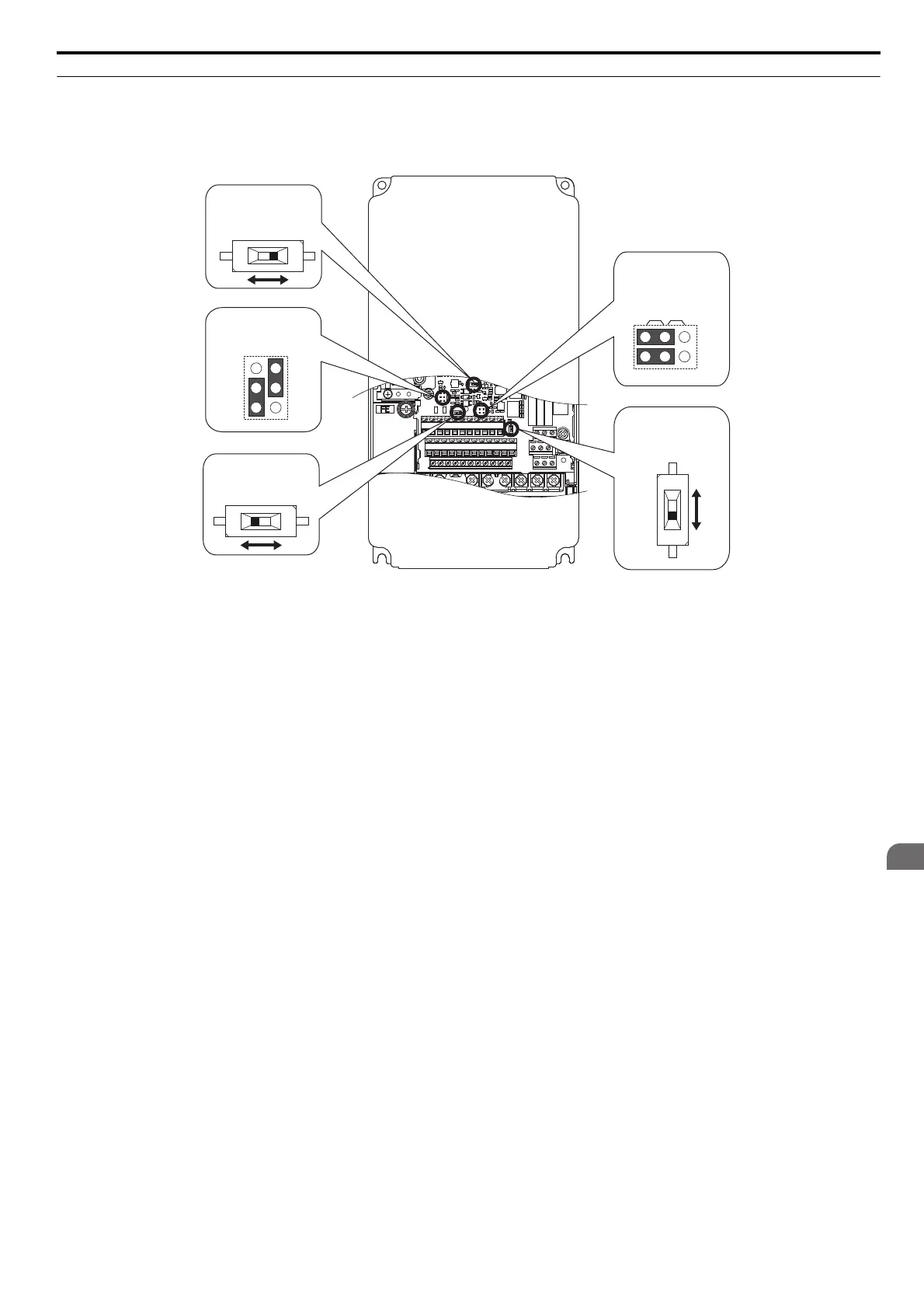
◆ Switches and Jumpers on the Terminal Board
The terminal board is equipped with several switches used to adapt the drive I/Os to the external control signals.
Figure 3.29 shows the location of these switches. Refer to Control I/O Connections on page 86 for setting instructions.
Figure 3.36
Figure 3.29 Locations of Jumpers and Switches on the Terminal Board
VI
DIP Switch S1
Terminal A2 Signal
Selection
PTC
AI
DIP Switch S4
Terminal A3 Analog/
PTC Input Sel.
Jumper S5
Terminal AM/FM Signal
Selection
Jumper S3
Terminal H1/H2
Sink/Source Sel.
DIP Switch S2
RS-422/RS-485
Termination Resistor
Off On
V
AM
FM
I
SIEP_C710616_35.book 85 ページ 2015年11月30日 月曜日 午後2時2分