3.9 Control Circuit Wiring
84 YASKAWA ELECTRIC SIEP C710616 35D YASKAWA AC Drive E1000 Technical Manual
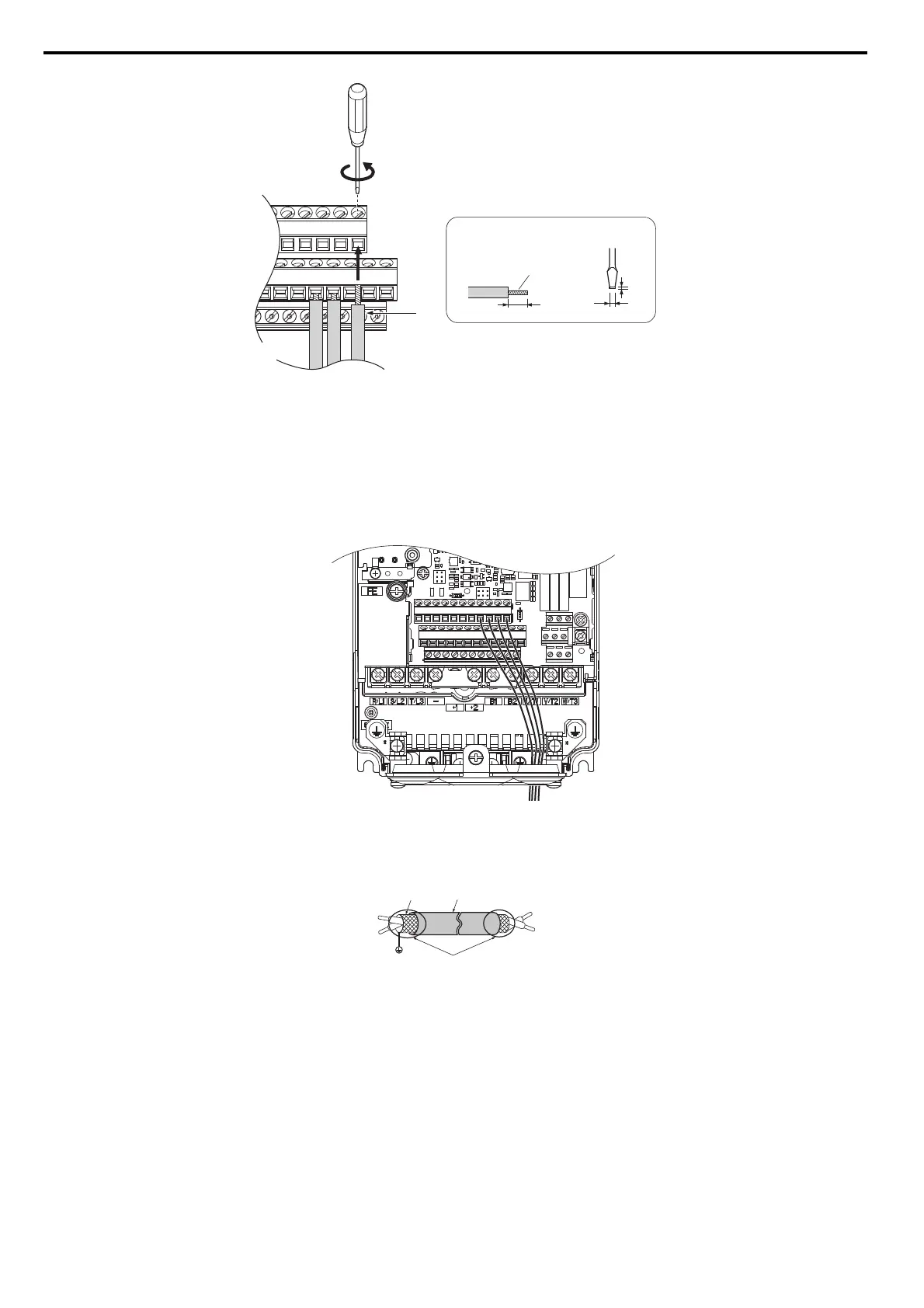
Figure 3.33
Figure 3.26 Terminal Board Wiring Guide
Figure 3.34
Figure 3.27 Terminal Board Wiring
When setting the frequency by analog reference from an external potentiometer, use shielded twisted-pair wires (treating
wire ends as shown in Figure 3.28 and connect the shield to the ground terminal of the drive.
Figure 3.35
Figure 3.28 Preparing the Ends of Shielded Cables
NOTICE: The signal lines between the drive and the operator station or peripheral equipment should not exceed 50 meters when
using an analog signal from a remote source to supply the frequency reference. Failure to comply could result in poor system
performance.
A – Loosen screw to insert wire. C – Avoid fraying wire strands when stripping
insulation from wire. Strip length 5.5 mm.
B – Single wire or stranded wire D – Blade depth of 0.4 mm or less
Blade width of 2.5 mm or less
A – Drive side D – Control device side
B – Connect shield to ground terminal of
drive.
E – Shield sheath (insulate with tape)
C – Insulation F – Shield
A
B
C
D
Preparing wire
terminal ends
F
C
D
E
B
SIEP_C710616_35.book 84 ページ 2015年11月30日 月曜日 午後2時2分