5.7 H: Terminal Functions
YASKAWA ELECTRIC SIEP C710616 35D YASKAWA AC Drive E1000 Technical Manual 199
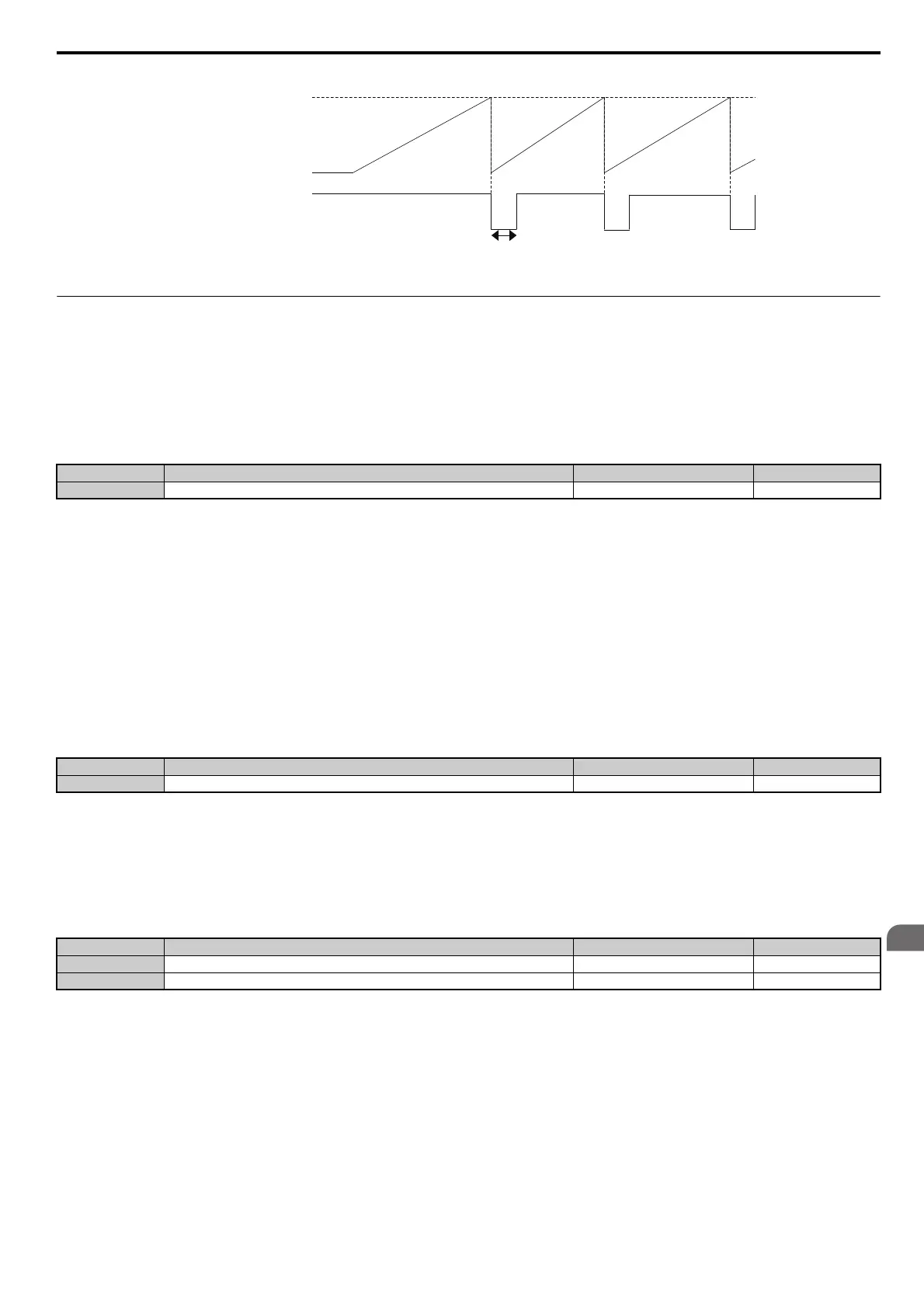
Figure 5.52
Figure 5.52 Watt Hour Output Example
◆ H3: Multi-Function Analog Inputs
The drive is equipped with three multi-function analog input terminals: A1, A2, and A3. See Table 5.30 for a listing of
the functions that can be set to these terminals.
■
H3-01: Terminal A1 Signal Level Selection
Selects the input signal level for analog input A1.
Setting 0: 0 to 10 Vdc
The input level is 0 to 10 Vdc. The minimum input level is limited to 0%, so that a negative input signal due to gain and
bias settings will be simply read as 0%.
Setting 1: –10 to 10 Vdc
The input level is –10 to 10 Vdc. If the resulting voltage is negative after being adjusted by gain and bias settings, then
the motor will rotate in reverse.
■
H3-02: Terminal A1 Function Selection
Selects the input signal level for analog input A3. Refer to Multi-Function Analog Input Terminal Settings on page 202
for instructions on how to adjust the signal level.
■
H3-03, H3-04: Terminal A1 Gain and Bias Settings
Parameter H3-03 sets the level of the selected input value that is equal to 10 Vdc input at terminal A1 (gain).
Parameter H3-04 sets the level of the selected input value that is equal to 0 V input at terminal A1 (bias).
Both can be used to adjust the characteristics of the analog input signal to terminal A1.
No. Name Setting Range Default
H3-01 Terminal A1 Signal Level Selection 0 to 1 0
No. Name Setting Range Default
H3-02 Terminal A1 Function Selection 0 to 31 0
No. Name Setting Range Default
H3-03 Terminal A1 Gain Setting -999.9 to 999.9% 100.0%
H3-04 Terminal A1 Bias Setting -999.9 to 999.9% 0.0%
0.2 s
H2-06
(Pulse Output Unit)
H2-01 to 03
㧔Multi-function Output)
Integral Power (every 100 ms)
OFF OFF
ON
SIEP_C710616_35.book 199 ページ 2015年11月30日 月曜日 午後2時2分