5.3 C: Tuning
YASKAWA ELECTRIC SIEP C710616 35D YASKAWA AC Drive E1000 Technical Manual 163
■ C4-02: Torque Compensation Primary Delay Time
Sets the delay time used for applying torque compensation.
Adjustment
Although C4-02 rarely needs to be changed, adjustments may help in the following situations:
• If the motor vibrates, increase C4-02.
• If the motor responds too slowly to changes in the load, decrease C4-02.
◆ C6: Carrier Frequency
■ C6-02: Carrier Frequency Selection
Parameter C6-02 sets the switching frequency of the drive’s output transistors. Changes to the switching frequency helps
lower audible noise and also reduces leakage current.
Note: 1. Increasing the carrier frequency above the default value automatically lowers the drive’s current rating. Refer to Rated Current
Depending on Carrier Frequency on page 164.
Settings:
Note: Swing PWM uses a carrier frequency of 2.0 kHz as a base, then applies a special PWM pattern to reduce the audible noise.
Guidelines for Carrier Frequency Parameter Setup
Note: The maximum cable length is 100 m when A1-02 = 5 (OLV/PM).
■ C6-03, C6-04, C6-05: Carrier Frequency Upper Limit, Lower Limit, Proportional Gain
Use these parameters to set a user defined or a variable carrier frequency. To set the upper and lower limits and the carrier
frequency proportional gain, first set C6-02 to F.
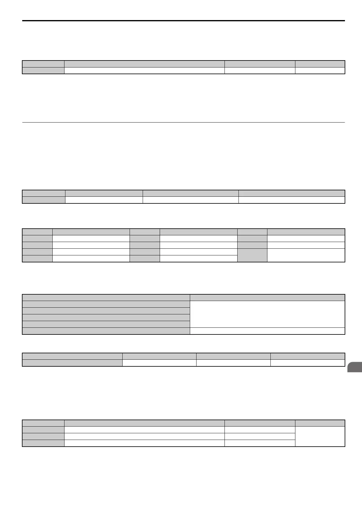
No. Parameter Name Setting Range Default
C4-02 Torque Compensation Primary Delay Time 0 to 60000 ms Determined by A1-02
No.
<1> The setting range is 1, 2, and F for models CIMR-E4A0515 to 4A1200.
Parameter Name Setting Range Default
C6-02 Carrier Frequency Selection 1 to F <1> Determined by A1-02, o2-04.
C6-02 Carrier Frequency C6-02 Carrier Frequency C6-02 Carrier Frequency
1 2.0 kHz 5 12.5 kHz 9 Swing PWM 3
2 5.0 kHz 6 15.0 kHz A Swing PWM 4
3 8.0 kHz 7 Swing PWM 1
F User defined (C6-03 to C6-05)
4 10.0 kHz 8 Swing PWM 2
Symptom
<1> The carrier frequency may need to be lowered if the motor cable is too long. Refer to the table below.
Remedy
Speed and torque are unstable at low speeds
Lower the carrier frequency.
Noise from the drive affects peripheral devices
Excessive leakage current from the drive
Wiring between the drive and motor is too long <1>
Audible motor noise is too loud Increase the carrier frequency or use Swing PWM.
Wiring Distance Up to 50 m Up to 100 m Greater than 100 m
Recommended setting value for C6-02 1 to F (up to 15 kHz) 1 to 2 (up to 5 kHz), 7 (Swing PWM) 1 (up to 2 kHz), 7 (Swing PWM)
No. Parameter Name Setting Range Default
C6-03
<1> The setting range is 1.0 to 5.0 for models CIMR-E4A0515 to 4A1200.
Carrier Frequency Upper Limit 1.0 to 15.0 kHz <1>
Determined by C6-02C6-04 Carrier Frequency Lower Limit (V/f Control only) 1.0 to 15.0 kHz <1>
C6-05 Carrier Frequency Proportional Gain (V/f Control only) 0 to 99 <1>
SIEP_C710616_35.book 163 ページ 2015年11月30日 月曜日 午後2時2分