1.5 Component Names
YASKAWA ELECTRIC SIEP C710616 35D YASKAWA AC Drive E1000 Technical Manual 39
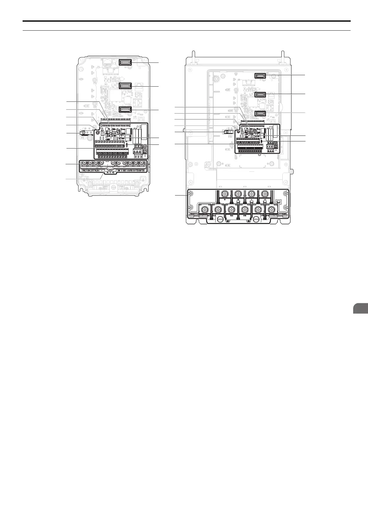
◆ Front Views
Figure 1.8
Figure 1.9 Front View of Drives
A – Terminal board connector H – Top protective cover to prevent
miswiring
B – DIP switch S1 (Refer to Terminal A2
Input Signal Selection on page 89)
I – Option card connector (CN5-C)
C – DIP switch S2 (Refer to MEMOBUS/
Modbus Termination on page 91)
J – Option card connector (CN5-B)
D – Jumper S3 (refer to Sinking/Sourcing
Mode Selection for Hardwire
Baseblock Inputs on page 86)
K – Option card connector (CN5-A)
E – Ground terminal L – Jumper S5 (Refer to Terminal AM/FM
Signal Selection on page 88)
F – Terminal board (Refer to Control
Circuit Wiring on page 79)
M – DIP Switch S4 (Refer to Terminal A3
Analog/PTC Input Selection on
page 88)
G – Main circuit terminal (Refer to Wiring
the Main Circuit Terminal on page 78)
I
K
J
H
G
CIMR-E2A0012F
L
M
G
CIMR-E2A0110A
K
J
I
A
F
E
B
C
D
L
M
A
F
E
B
C
D
SIEP_C710616_35.book 39 ページ 2015年11月30日 月曜日 午後2時2分