3.8 Main Circuit Wiring
78 YASKAWA ELECTRIC SIEP C710616 35D YASKAWA AC Drive E1000 Technical Manual
■ Ground Wiring
Follow the precautions to wire the ground for one drive or a series of drives.
WARNING! Electrical Shock Hazard. Make sure the protective earthing conductor complies with technical standards and local safety
regulations. Because the leakage current exceeds 3.5 mA in models CIMR-E4A0414 and larger, IEC/EN 61800-5-1 states that
either the power supply must be automatically disconnected in case of discontinuity of the protective earthing conductor or a protective
earthing conductor with a cross-section of at least 10 mm
2
(Cu) or 16 mm
2
(Al) must be used. Failure to comply may result in death or
serious injury.
WARNING! Electrical Shock Hazard. Always use a ground wire that complies with technical standards on electrical equipment and
minimize the length of the ground wire. Improper equipment grounding may cause dangerous electrical potentials on equipment
chassis, which could result in death or serious injury.
WARNING! Electrical Shock Hazard. Be sure to ground the drive ground terminal. Improper equipment grounding could result in death
or serious injury by contacting ungrounded electrical equipment.
NOTICE: Do not share the ground wire with other devices such as welding machines or large-current electrical equipment. Improper
equipment grounding could result in drive or equipment malfunction due to electrical interference.
NOTICE: When using more than one drive, ground multiple drives according to instructions. Improper equipment grounding could
result in abnormal operation of drive or equipment.
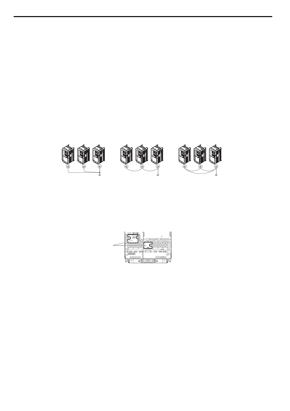
Refer to Figure 3.20 when using multiple drives. Do not loop the ground wire.
Figure 3.27
Figure 3.20 Multiple Drive Wiring
■ Wiring the Main Circuit Terminal
WARNING! Electrical Shock Hazard. Shut off the power supply to the drive before wiring the main circuit terminals. Failure to comply
may result in death or serious injury.
Wire the main circuit terminals after the terminal board has been properly grounded.
Models CIMR-E2A0004 through 0081 and 4A0002 through 0044 have a cover placed over the DC bus and braking
circuit terminals prior to shipment to help prevent miswiring. Cut away covers as needed for terminals using wire cutters.
Figure 3.28
Figure 3.21 Protecting Cover to Prevent Miswiring (CIMR-E2A0056)
■ Main Circuit Configurations
Refer to Main Circuit Configurations on page 61 when wiring terminals on the drive’s main power circuit.
A – Protecting Cover
SIEP_C710616_35.book 78 ページ 2015年11月30日 月曜日 午後2時2分