3.15 Wiring Checklist
YASKAWA ELECTRIC SIEP C710616 35D YASKAWA AC Drive E1000 Technical Manual 93
3.15 Wiring Checklist
No. Item Page
Drive, peripherals, option cards
1 Check drive model number to ensure receipt of correct model. 27
2 Make sure you have the correct braking options, DC reactors, noise filters, and other peripheral devices. 333
3 Check the option card model number. 333
Installation area and physical setup
4 Ensure that the area surrounding the drive complies with specifications. 44
Power supply voltage, output voltage
5 The voltage from the power supply should be within the input voltage specification range of the drive. 170
6 The voltage rating for the motor should match the drive output specifications.
29
390
7 Verify that the drive is properly sized to run the motor.
29
390
Main circuit wiring
8 Confirm proper branch circuit protection as specified by national and local codes. 58
9
Properly wire the power supply to drive terminals R/L1, S/L2, and T/L3.
Note: Confirm the following when wiring models CIMR-E4A0930 and 4A1200:
• Remove the jumpers shorting terminals R/L1-R1/L11, S/L2-S1/L21, and T/L3-T1/L31 when operating with 12-phase rectification. Refer to
12-Phase Rectification on page 62 for more information.
• When operating without 12-phase rectification, properly wire terminals R1/L11, S1/L21, and T1/L31 in addition to terminals R1/L1, S1/
L2, and T1/L3.
61
10
Properly wire the drive and motor together.
The motor lines and drive output terminals R/T1, V/T2, and W/T3 should match in order to produce the desired phase order. If the phase order
is incorrect, the drive will rotate in the opposite direction.
77
11 Use 600 Vac vinyl-sheathed wire for the power supply and motor lines. 73
12
Use the correct wire gauges for the main circuit. Refer to Wire Gauges and Tightening Torque on page 73. 73
• When using comparatively long motor cable, calculate the amount of voltage drop. 73
• If the cable between the drive and motor exceeds 50 m, adjust the carrier frequency set to C6-02 accordingly. 77
13 Properly ground the drive. Review page 78. 78
14
Tightly fasten all terminal screws (control circuit terminals, grounding terminals).
Refer to Wire Gauges and Tightening Torque on page 73.
73
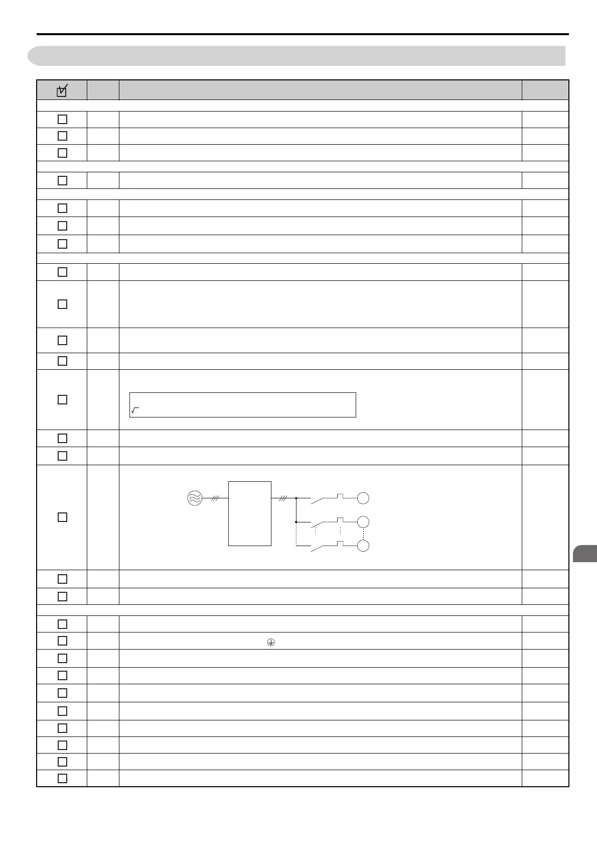
15
Set up overload protection circuits when running multiple motors from a single drive.
Note: Close MC1 through MCn before operating the drive. (MC1 through MCn cannot be switched off during run.)
–
16
If using dynamic braking options, install a magnetic contactor. Properly install the resistor, and ensure that overload protection shuts off the
power supply.
340
17 Verify phase advancing capacitors, input noise filters, or ground fault circuit interrupters are NOT installed on the output side of the drive. –
Contr
ol circuit
wiring
18 Use twisted-pair line for all drive control circuit wiring. 79
19
Ground the shields of shielded wiring to the GND terminal.
83
20
If using a 3-wire sequence, properly set parameters for multi-function contact input terminals S1 through S8, and properly wire control
circuits.
–
21 Properly wire any option cards. 82
22
Check for any other wiring mistakes.
Only use a multimeter to check wiring.
–
23
Properly fasten the control circuit terminal screws in the drive.
Refer to Wire Gauges and Tightening Torque on page 73.
73
24 Pick up all wire clippings. –
25 Ensure that no frayed wires on the terminal block are touching other terminals or connections. –
26 Properly separate control circuit wiring and main circuit wiring. –
27 Analog signal line wiring should not exceed 50 m. –
3 x wire resistance (Ω/km) x cable length (m) x motor rated current (A) x 10
-3
Motor rated voltage (V) x 0.02 ≥
M1
OL1
OL2
OLn
MC1
MC2
MCn
M2
Mn
Drive
MC1 - MCn
OL 1 - OLn
... magnetic contactor
... thermal relay
Power supply
SIEP_C710616_35.book 93 ページ 2015年11月30日 月曜日 午後2時2分