2.2 Mechanical Installation
48 YASKAWA ELECTRIC SIEP C710616 35D YASKAWA AC Drive E1000 Technical Manual
Installation Types and Required Materials
There are two ways the digital operator can be mounted to an enclosure:
1.
External/face-mount installs the operator outside the enclosure panel
2. Internal/flush-mount installs the operator inside the enclosure panel
Table 2.2 Digital Operator Installation Methods and Required Tools
Note: Prevent foreign matter such as metal shavings or wire clippings from falling into the drive during installation and project
construction. Failure to comply could result in damage to the drive. Place a temporary cover over the top of the drive during
installation. Remove the temporary cover before startup, as the cover will reduce ventilation and cause the drive to overheat.
External/Face-Mount
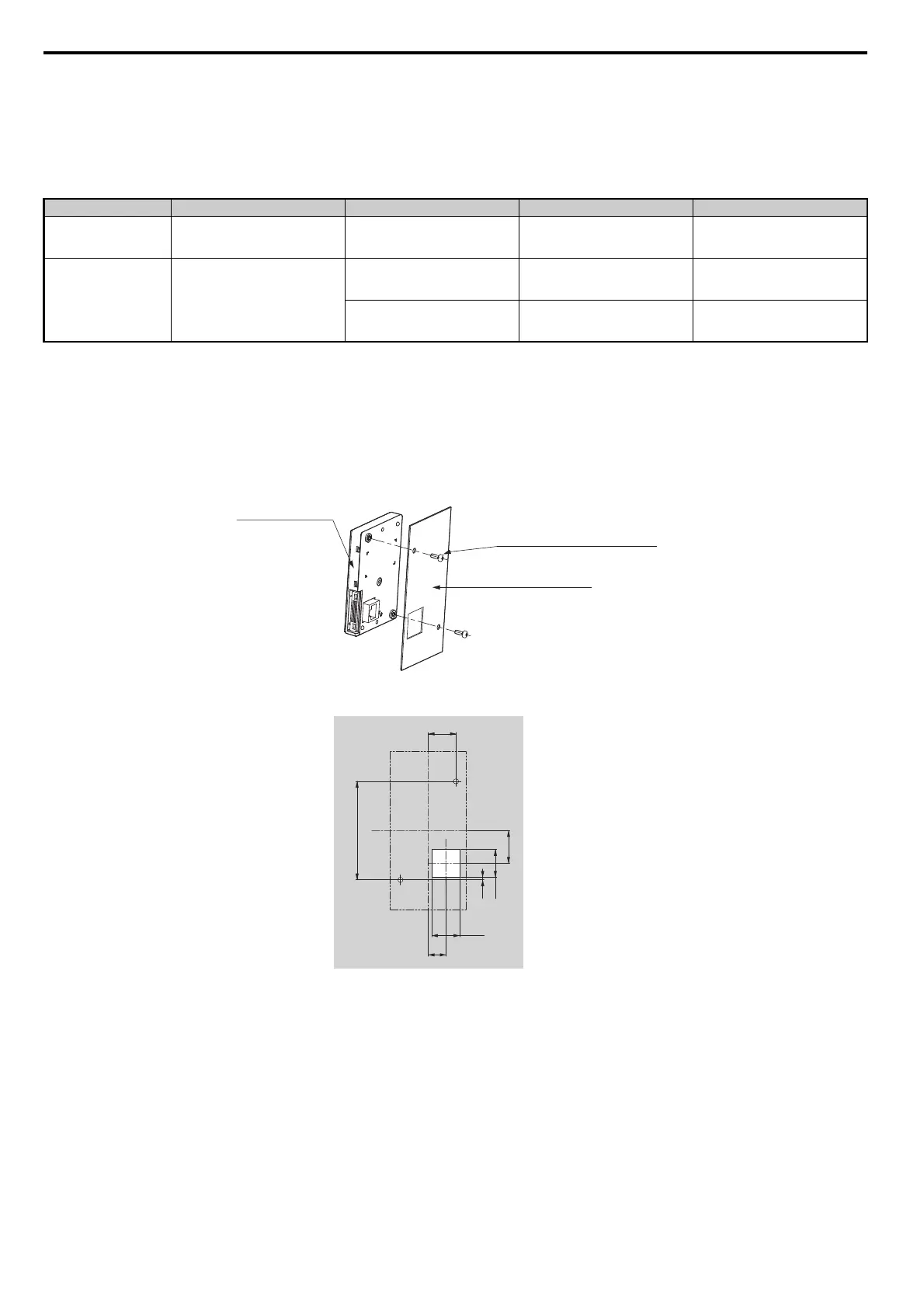
1. Cut an opening in the enclosure panel for the digital operator as shown in Figure 2.10.
2. Position the digital operator so the display faces outwards, and mount it to the enclosure panel as shown in
Figure 2.9.
Figure 2.8
Figure 2.9 External/Face-Mount Installation
Figure 2.9
Figure 2.10 Panel Cut-Out Dimensions (External/Face-Mount Installation)
Internal/Flush-Mount
An internal flush-mount requires an installation support set that must be purchased separately. Contact your Yaskawa
representative to order an installation support set and mounting hardware. Figure 2.11 illustrates how to attach the
Installation Support Set A.
1.
Cut an opening in the enclosure panel for the digital operator as shown in Figure 2.12.
2. Mount the digital operator to the installation support.
3. Mount the installation support set and digital operator to the enclosure panel.
Installation Method Description Installation Support Sets Model Required Tools
External/Face-Mount
Simplified installation with the digital
operator is mounted on the outside of
the panel with two screws.
– – Phillips screwdriver (#1)
Internal/Flush-Mount
Encloses the digital operator in the
panel. The digital operator is flush
with the outside of the panel.
Installation Support Set A
(for mounting with screws through
holes in the panel)
EZZ020642A Phillips screwdriver (#1, #2)
Installation Support Set B
(for use with threaded studs that are
fixed to the panel)
EZZ020642B
Phillips screwdriver (#1)
Wrench (7 mm)
Digital Operator
M3 × 6
Phillips recessed
pan head machine screw × 2
Enclosure panel
Unit: mm
SIEP_C710616_35.book 48 ページ 2015年11月30日 月曜日 午後2時2分