3.9 Control Circuit Wiring
YASKAWA ELECTRIC SIEP C710616 35D YASKAWA AC Drive E1000 Technical Manual 81
■ Output Terminals
Table 3.7 lists the output terminals on the drive. Text in parenthesis indicates the default setting for each multi-function
output.
Table 3.7 Control Circuit Output Terminals
Figure 3.30
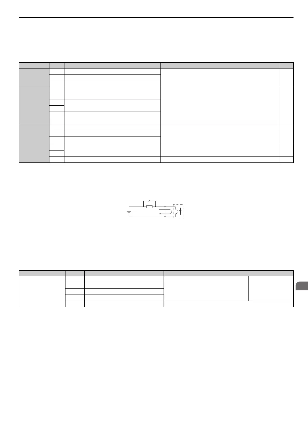
Figure 3.23 Connecting a Suppression Diode
■ Serial Communication Terminals
Table 3.8 Control Circuit Terminals: Serial Communications
Type
<1> Refrain from assigning functions to digital outputs that involve frequent switching, as doing so may shorten relay performance life. Switching
life is estimated at 200,000 times (assumes 1 A, resistive load).
<2> Connect a flywheel diode as shown in the Figure 3.23 when driving a reactive load such as a relay coil. Make sure the diode rating is greater
than the circuit voltage.
No. Terminal Name (Function) Function (Signal Level) Default Setting Page
Fault Relay Output
MA
N.O.
30 Vdc, 10 mA to 1 A; 250 Vac, 10 mA to 1 A
Minimum load: 5 Vdc, 10 mA
190
MB
N.C. output
MC
Fault output common
Multi-Function
Digital Output
<1>
M1
Multi-function digital output (During run)
30 Vdc, 10 mA to 1 A; 250 Vac, 10 mA to 1 A
Minimum load: 5 Vdc, 10 mA
<2>
190
M2
M3
Multi-function digital output (Zero Speed)
M4
M5
Multi-function digital output (Speed Agree 1)
M6
Monitor Output
MP
Pulse train output (Output frequency) 32 kHz (max) 206
FM
Analog monitor output 1 (Output frequency)
-10 to +10 Vdc, 0 to +10 Vdc, or 4-20 mA
Use jumper S5 on the terminal board to select between voltage or current output
signals.
205
AM
Analog monitor output 2 (Output current)
DM+
Hardwire Baseblock monitor output
Outputs status of Hardwire Baseblock function. Closed when both Hardwire
Baseblock channels are closed. Up to +48 Vdc 50 mA
–
DM-
AC
Monitor common 0 V –
A – External power, 48 V max. C – Coil
B – Suppression diode D – 50 mA or less
Type
<1> Enable the termination resistor in the last drive in a MEMOBUS network by setting DIP switch S2 to the ON position. For more information on
the termination resistor, see Control I/O Connections on page 86.
No. Signal Name Function (Signal Level)
MEMOBUS/Modbus
Communication
<1>
R+
Communications input (+)
MEMOBUS/Modbus communication: Use a RS-485 or
RS-422 cable to connect the drive.
RS-422/RS-485
MEMOBUS/Modbus
communication protocol
115.2 kbps (max.)
R-
Communications input (-)
S+
Communications output (+)
S-
Communications output (-)
IG
Shield ground 0 V
B
C
D
SIEP_C710616_35.book 81 ページ 2015年11月30日 月曜日 午後2時2分