B.3 Parameter Table
YASKAWA ELECTRIC SIEP C710616 35D YASKAWA AC Drive E1000 Technical Manual 379
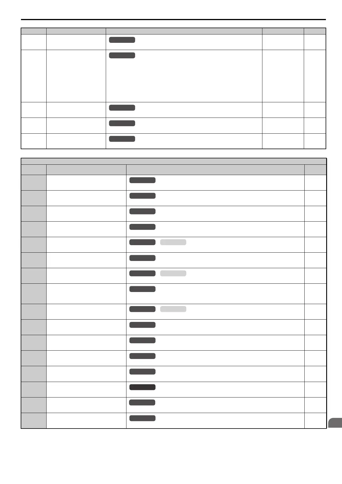
H3-13
(41BH)
Analog Input Filter Time Constant
Sets a primary delay filter time constant for terminals A1, A2, and A3. Used for noise filtering.
Default: 0.03 s
Min: 0.00 s
Max: 2.00 s
201
H3-14
(41CH)
Analog Input Terminal Enable
Selection
Determines which of the analog input terminals will be enabled when a digital input
programmed for “Analog input enable” (H1- = C) is activated.
1: A1 only enable
2: A2 only enable
3: A1 and A2 only enable
4: A3 only enable
5: A1 and A3 enable
6: A2 and A3 enable
7: All analog input terminals enabled
Default: 7
Min: 1
Max: 7
202
H3-16
(2F0H)
Terminal A1 Offset
Adds an offset when the analog signal to terminal A1 is at 0 V.
Default: 0
Min: -500
Max: 500
202
H3-17
(2F1H)
Terminal A2 Offset
Adds an offset when the analog signal to terminal A2 is at 0 V.
Default: 0
Min: -500
Max: 500
202
H3-18
(2F2H)
Terminal A3 Offset
Adds an offset when the analog signal to terminal A3 is at 0 V.
Default: 0
Min: -500
Max: 500
202
H3 Multi-Function Analog Input Settings
H3-
Setting
Function Description Page
0 Frequency Bias
10 V = E1-04 (maximum output frequency)
202
1 Frequency Gain
0 to 10 V signal allows a setting of 0 to 100%. -10 to 0 V signal allows a setting of -100 to 0%.
203
2
Auxiliary Frequency Reference 1 (used as a
Multi-Step Speed 2)
10 V = E1-04 (maximum output frequency)
203
3
Auxiliary Frequency Reference 2 (3rd step
analog)
10 V = E1-04 (maximum output frequency)
203
4 Output Voltage Bias
10 V = E1-05 (motor rated voltage)
203
5 Accel/Decel Time Gain
10V=100% Accel/Decel Gain
203
6 DC Injection Braking Current
10 V = Drive rated current
203
7 Torque Detection Level
10 V = Drive rated current (V/f)
10 V = Motor rated torque (OLV/PM)
203
8 Stall Prevention Level During Run
10 V = Drive rated current
204
9 Output Frequency Lower Limit Level
10 V = E1-04 (maximum output frequency)
204
B PI Feedback
10 V=100% Feed back
204
CPI Setpoint
10 V=100% PI setpoint
204
D Frequency Bias
10 V = E1-04 (maximum output frequency)
204
E Motor Temperature (PTC input)
10 V = 100%
204
F Through Mode
Set this value when using the terminal in the pass-through mode.
204
16 Differential PI Feedback
10 V = 100%
204
No.(Addr.) Name Description Setting Page
All Modes
All Modes
All Modes
All Modes
All Modes
OLV/PMV/f
OLV/PMV/f
OLV/PMV/f
All Modes
SIEP_C710616_35.book 379 ページ 2015年11月30日 月曜日 午後2時2分