B.3 Parameter Table
380 YASKAWA ELECTRIC SIEP C710616 35D YASKAWA AC Drive E1000 Technical Manual
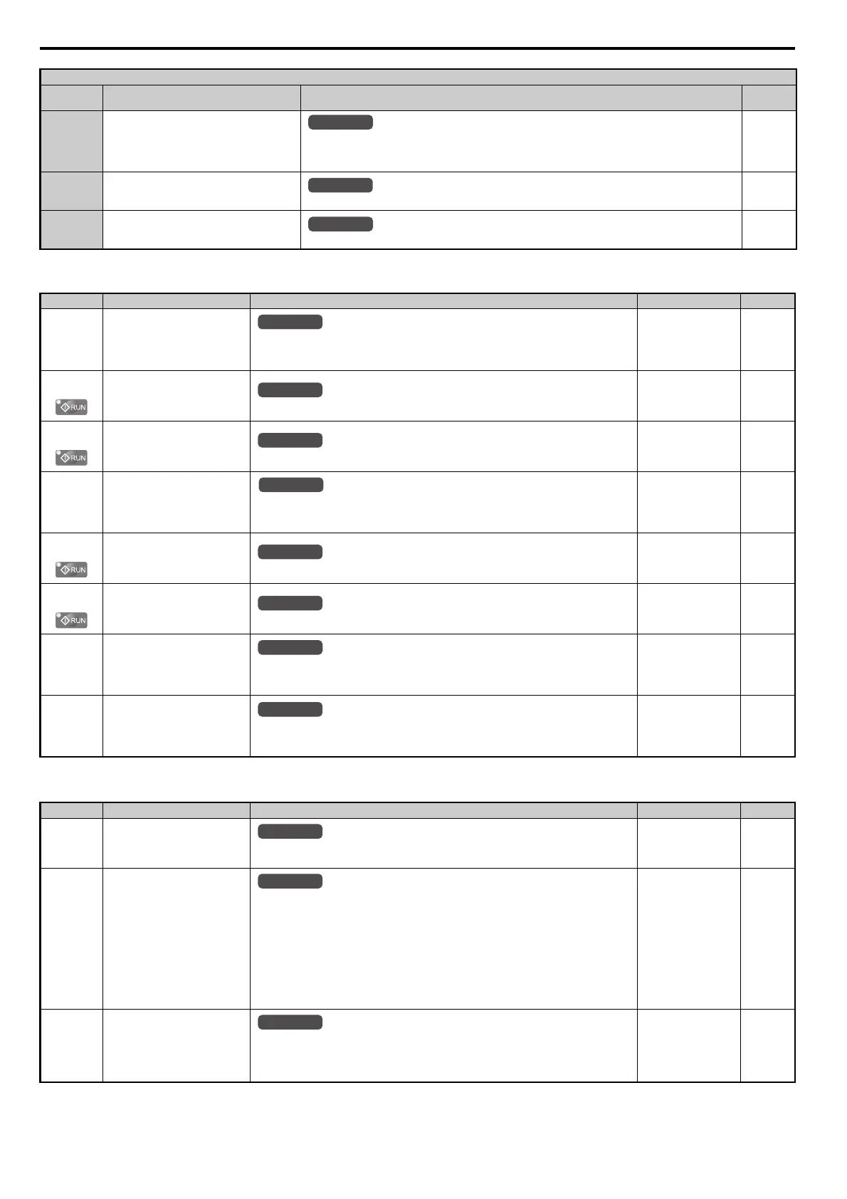
■ H4: Analog Outputs
■ H5: MEMOBUS/Modbus Serial Communication
17 Motor Thermistor (NTC)
10 V = -9°C
0 V = 234°C
Note: This function is available in models CIMR-E4A0930 and 4A1200.
204
1F Through Mode
Set this value when using the terminal in the pass-through mode.
204
30 to 32 DriveWorksEZ Analog Input 1 to 3
Output is determined by the function selected using DWEZ.
204
No.(Addr.) Name Description Setting Page
H4-01
(41DH)
Multi-Function Analog Output
Terminal FM Monitor Selection
Selects the data to be output through multi-function analog output terminal FM.
Set the desired monitor parameter to the digits available in U-. For example, enter “103”
for U1-03.
Default: 102
Min: 000
Max: 999
205
H4-02
(41EH)
Multi-Function Analog Output
Terminal FM Gain
Sets the signal level at terminal FM that is equal to 100% of the selected monitor value.
Default: 100.0%
Min: -999.9%
Max: 999.9%
205
H4-03
(41FH)
Multi-Function Analog Output
Terminal FM Bias
Sets the bias value added to the terminal FM output signal.
Default: 0.0%
Min: -999.9%
Max: 999.9%
205
H4-04
(420H)
Multi-Function Analog Output
Terminal AM Monitor Selection
Selects the data to be output through multi-function analog output terminal AM.
Set the desired monitor parameter to the digits available in U-. For example, enter “103”
for U1-03.
Default: 103
Min: 000
Max: 999
205
H4-05
(421H)
Multi-Function Analog Output
Terminal AM Gain
Sets the signal level at terminal AM that is equal to 100% of the selected monitor value.
Default: 50.0%
Min: -999.9%
Max: 999.9%
205
H4-06
(422H)
Multi-Function Analog Output
Terminal AM Bias
Sets the bias value added to the terminal AM output signal.
Default: 0.0%
Min: -999.9%
Max: 999.9%
205
H4-07
(423H)
Multi-Function Analog Output
Terminal FM Signal Level
Selection
0: 0 to 10 V
1: –10 to 10 V
2: 4 to 20 mA
Default: 0
Min: 0
Max: 1
206
H4-08
(424H)
Multi-Function Analog Output
Terminal AM Signal Level
Selection
0: 0 to 10 V
1: –10 to 10 V
2: 4 to 20 mA
Default: 0
Min: 0
Max: 1
206
No.(Addr.) Name Description Setting Page
H5-01
(425H)
<32>
Drive Node Address
Selects drive station node number (address) for MEMOBUS/Modbus terminals R+, R-, S+, S-.
Cycle power for the setting to take effect.
Default: 1F
Min: 0
Max: FFH
416
H5-02
(426H)
Communication Speed Selection
0: 1200 bps
1: 2400 bps
2: 4800 bps
3: 9600 bps
4: 19200 bps
5: 38400 bps
6: 57600 bps
7: 76800 bps
8: 115200 bps
Cycle power for the setting to take effect.
Default: 3
Min: 0
Max: 8
416
H5-03
(427H)
Communication Parity Selection
0: No parity
1: Even parity
2: Odd parity
Cycle power for the setting to take effect.
Default: 0
Min: 0
Max: 2
416
H3 Multi-Function Analog Input Settings
H3-
Setting
Function Description Page
All Modes
All Modes
All Modes
All Modes
All Modes
All Modes
All Modes
All Modes
All Modes
All Modes
All Modes
All Modes
SIEP_C710616_35.book 380 ページ 2015年11月30日 月曜日 午後2時2分

 Loading...


