B.3 Parameter Table
YASKAWA ELECTRIC SIEP C710616 35D YASKAWA AC Drive E1000 Technical Manual 383
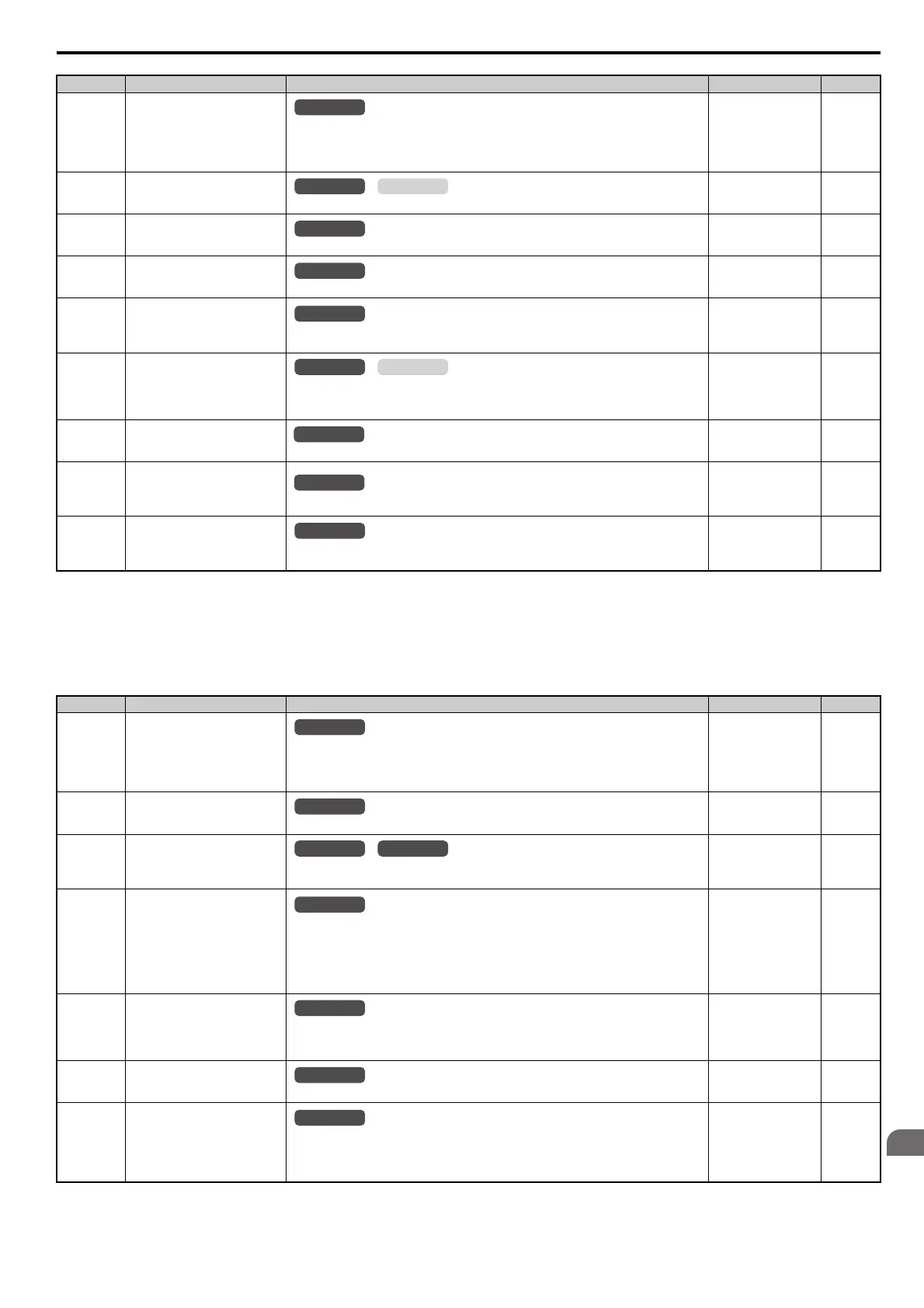
■ L3: Stall Prevention
L2-03
(487H)
Momentary Power Loss Minimum
Baseblock Time
Sets the minimum wait time for residual motor voltage decay before the drive output
reenergizes after performing Power Loss Ride-Thru.
Increasing the time set to L2-03 may help if overcurrent or overvoltage occur during Speed
Search or during DC Injection Braking.
Default:
<9>
Min: 0.1 s
Max: 5.0 s
219
L2-04
(488H)
Momentary Power Loss Voltage
Recovery Ramp Time
Sets the time for the output voltage to return to the preset V/f pattern during Speed Search.
Default:
<9>
Min: 0.0 s
Max: 5.0 s
219
L2-05
(489H)
Undervoltage Detection Level
(Uv)
Sets the DC bus undervoltage trip level.
Default:
<18> <33>
Min: 150 Vdc
Max: 210 Vdc
<18>
219
L2-06
(48AH)
KEB Deceleration Time
Sets the time required to decelerate from the speed when KEB was activated to zero speed.
Default: 0.00 s
Min: 0.00 s
Max: 6000.0 s
<12>
220
L2-07
(48BH)
KEB Acceleration Time
Sets the time to accelerate to the frequency reference when momentary power loss is over. If set
to 0.0, the active acceleration time is used.
Default: 0.00 s
Min: 0.00 s
Max: 6000.0 s
<12>
220
L2-08
(48CH)
Frequency Gain at KEB Start
Sets the percentage of output frequency reduction at the beginning of deceleration when the
KEB Ride-Thru function is started.
Reduction = (slip frequency before KEB) × L2-08 × 2
Default: 100%
Min: 0%
Max: 300%
220
L2-10
(48EH)
KEB Detection Time (Minimum
KEB Time)
Sets the time to perform KEB Ride-Thru.
Default: 50 ms
Min: 0 ms
Max: 2000 ms
220
L2-11
(461H)
DC Bus Voltage Setpoint during
KEB
Sets the desired value of the DC bus voltage during KEB Ride-Thru.
Default:
<18> <33>
[E1-01] × 1.22
Min: 150 Vdc
Max: 400 Vdc
<18>
220
L2-29
(475H)
KEB Method Selection
0: Single Drive KEB Ride-Thru 1
1: Single Drive KEB Ride-Thru 2
Default: 0
Min: 0
Max: 1
220
<9> Default setting is determined by the drive model (o2-04).
<12> Setting range value is dependent on the units selected for the accel/decel time (C1-10). When C1-10 = 0 (units of 0.01 s), the setting range
becomes 0.00 to 600.00 s.
<18> Values shown here are for 200 V class drives. Double the value when using a 400 V class drive.
<33> Default setting value is dependent on the setting for the input voltage (E1-01).
No. (Addr.) Name Description Setting Page
L3-01
(48FH)
Stall Prevention Selection during
Acceleration
0: Disabled.
1: Enable.
2: Intelligent Stall Prevention.
Note: Setting 2 is not available when using OLV/PM.
Default: 1
Min: 0
Max: 2
221
L3-02
(490H)
Stall Prevention Level during
Acceleration
Used when L3-01 = 1 or 2. 100% is equal to the drive rated current.
Default:
<35>
Min: 0%
Max: 150%
<35>
222
L3-03
(491H)
Stall Prevention Limit during
Acceleration
Sets Stall Prevention lower limit during acceleration when operating in the constant power
range. Set as a percentage of the drive’s rated current.
Default: 50%
Min: 0%
Max: 100%
222
L3-04
(492H)
Stall Prevention Selection during
Deceleration
0: Disabled. Deceleration at the active deceleration rate. An ov fault may occur.
1: General-purpose Stall Prevention. Deceleration is paused when the DC bus voltage exceeds
the Stall Prevention level.
2: Intelligent Stall Prevention. Decelerate as fast as possible while avoiding ov faults.
4: Overexcitation Deceleration 1. Decelerates while increasing the motor flux.
5: Overexcitation Deceleration 2. Adjust the deceleration rate according to the DC bus voltage.
Default: 1
Min: 0
Max: 5
<34>
223
L3-05
(493H)
Stall Prevention Selection during
Run
0: Disabled. Drive runs at a set frequency. A heavy load may cause speed loss.
1: Decelerate using C1-02.
2: Decelerate using C1-04.
Default: 1
Min: 0
Max: 2
224
L3-06
(494H)
Stall Prevention Level during Run
Enabled when L3-05 is set to 1 or 2. 100% is equal to the drive rated current.
Default:
<35>
Min: 30%
Max: 150%
<35>
224
L3-11
(4C7H)
Overvoltage Suppression Function
Selection
Enables or disables the ov suppression function, which allows the drive to change the output
frequency as the load changes to prevent an ov fault.
0: Disabled
1: Enabled
Default: 0
Min: 0
Max: 1
225
No. (Addr.) Name Description Setting Page
All Modes
OLV/PMV/f
All Modes
All Modes
All Modes
OLV/PMV/f
All Modes
All Modes
All Modes
OLV/PMV/f
All Modes
All Modes
All Modes
All Modes
SIEP_C710616_35.book 383 ページ 2015年11月30日 月曜日 午後2時2分