5.8 L: Protection Functions
220 YASKAWA ELECTRIC SIEP C710616 35D YASKAWA AC Drive E1000 Technical Manual
■ L2-06: KEB Deceleration Time
Sets the time to decelerate from the frequency reference at the time KEB Ride-Thru was initiated down to zero speed.
■
L2-07: KEB Acceleration Time
Sets the time to reaccelerate from the speed when KEB was deactivated to the frequency reference.
When set to 0.0 s, the drive will accelerate back up to speed according to the active deceleration time set by C1-01, C1-
03.
■
L2-08: Frequency Gain at KEB Start
When the KEB Ride-Thru command is input, the output frequency is reduced in a single step in order to quickly get the
motor into a regenerative state. The amount of this frequency reduction can be calculated using the formula below. Note
that L2-08 can only be used with induction motors.
Amount of reduction = Slip frequency prior to KEB × (L2-08) × 2
■
L2-10: KEB Detection Time (Minimum KEB Time)
Parameter L2-10 determines how long KEB Ride-Thru must operate once it is triggered. Also refer to KEB Ride-Thru
End Detection on page 216.
■
L2-11: DC Bus Voltage Setpoint during KEB
Determines the setpoint (target value) for the DC bus voltage during Single KEB Ride-Thru 2. For Single KEB Ride-
Thru 1, parameter L2-11 defines the voltage level to end KEB Ride-Thru.
■
L2-29: KEB Method Selection
Selects the way the Kinetic Energy Buffering function operates.
The KEB function is not active when L2-01 is set to 4.
Note: If a multi function input is set for Single KEB Ride-Thru 2 (H1- = 7A, 7B) the setting of L2-29 is disregarded and the KEB
mode equal to L2-29 = 1 is automatically selected.
Setting 0: Single Drive KEB Ride-Thru 1
Setting 1: Single Drive KEB Ride-Thru 2
Refer to KEB Ride-Thru Function on page 215 for detailed explanations.
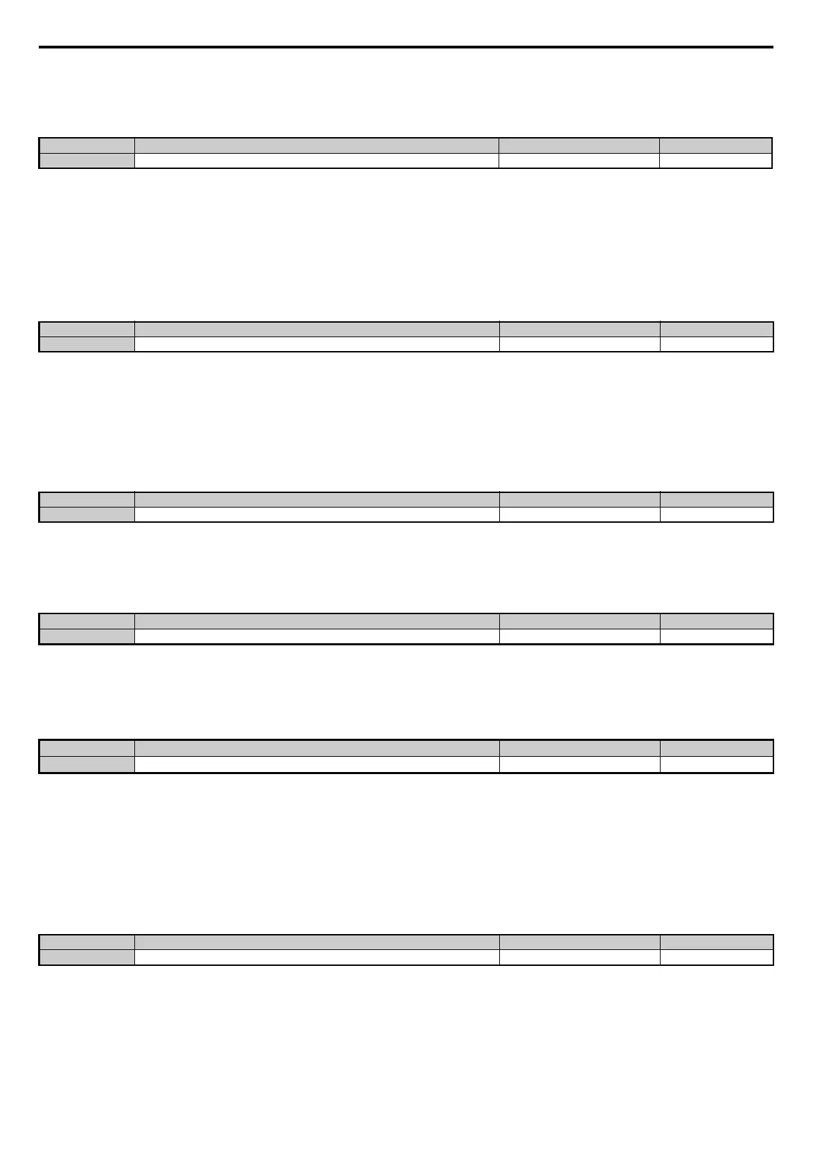
No.
<1> Setting range is determined by the accel/decel time units set in C1-10. If the time is set in units of 0.01 s (C1-10 = 0), the setting range
becomes 0.00 to 600.00 s.
Name Setting Range Default
L2-06 KEB Deceleration Time 0.00 to 6000.0 s <1> 0.00 s
No. Name Setting Range Default
L2-07 KEB Acceleration Time 0.00 to 6000.0 s 0.00 s
No. Name Setting Range Default
L2-08 Frequency Gain at KEB Start 0 to 300% 100%
No. Name Setting Range Default
L2-10 KEB Detection Time 0 to 2000 ms 50 ms
No.
<1> Values are for 200 V class drives and must be doubled for 400 V class drives.
<2> Default setting is determined by E1-01.
Name Setting Range Default
L2-11 DC Bus Voltage Setpoint during KEB
150 to 400 Vdc
<1> <2>
No. Name Setting Range Default
L2-29 KEB Method Selection 0, 1 0
SIEP_C710616_35.book 220 ページ 2015年11月30日 月曜日 午後2時2分