5.8 L: Protection Functions
YASKAWA ELECTRIC SIEP C710616 35D YASKAWA AC Drive E1000 Technical Manual 223
■ L3-22: Deceleration Time at Stall Prevention during Acceleration
Sets the brief deceleration time used when stalling occurs while accelerating a PM motor. When set to 0, this function is
disabled and the drive will decelerate at the selected deceleration time when stalling occurs.
The function is effective only in Open Loop Vector Control for PM motors and if parameter L3-01 is set to 1.
■
L3-04: Stall Prevention Selection during Deceleration
Stall Prevention during deceleration can control the deceleration based on the DC bus voltage and prevent an overvoltage
fault caused by high inertia or rapid deceleration.
Setting 0: Disabled
When this setting is used, the drive decelerates according to the set deceleration time. With high inertia loads or rapid
deceleration, an overvoltage (ov) fault may occur. In this case use braking options or switch to another L3-04 selection.
Setting 1: General-purpose Stall Prevention
With this setting the drive tries to decelerate within the set deceleration time. When the DC bus voltage exceeds the Stall
Prevention level, the drive pauses deceleration. Deceleration continues as soon as the DC bus voltage drops below that
level. Stall Prevention may be triggered repeatedly to avoid an overvoltage fault. The DC bus voltage level for Stall
Prevention depends on the input voltage setting E1-01.
Note: 1. This setting should not be used in combination with a Dynamic Braking Resistor or other braking options. If Stall Prevention during
deceleration is enabled, it will be triggered before the braking resistor option can operate.
2. This method may lengthen the total deceleration time compared to the set value. If this is not appropriate for the application consider
using a braking option.
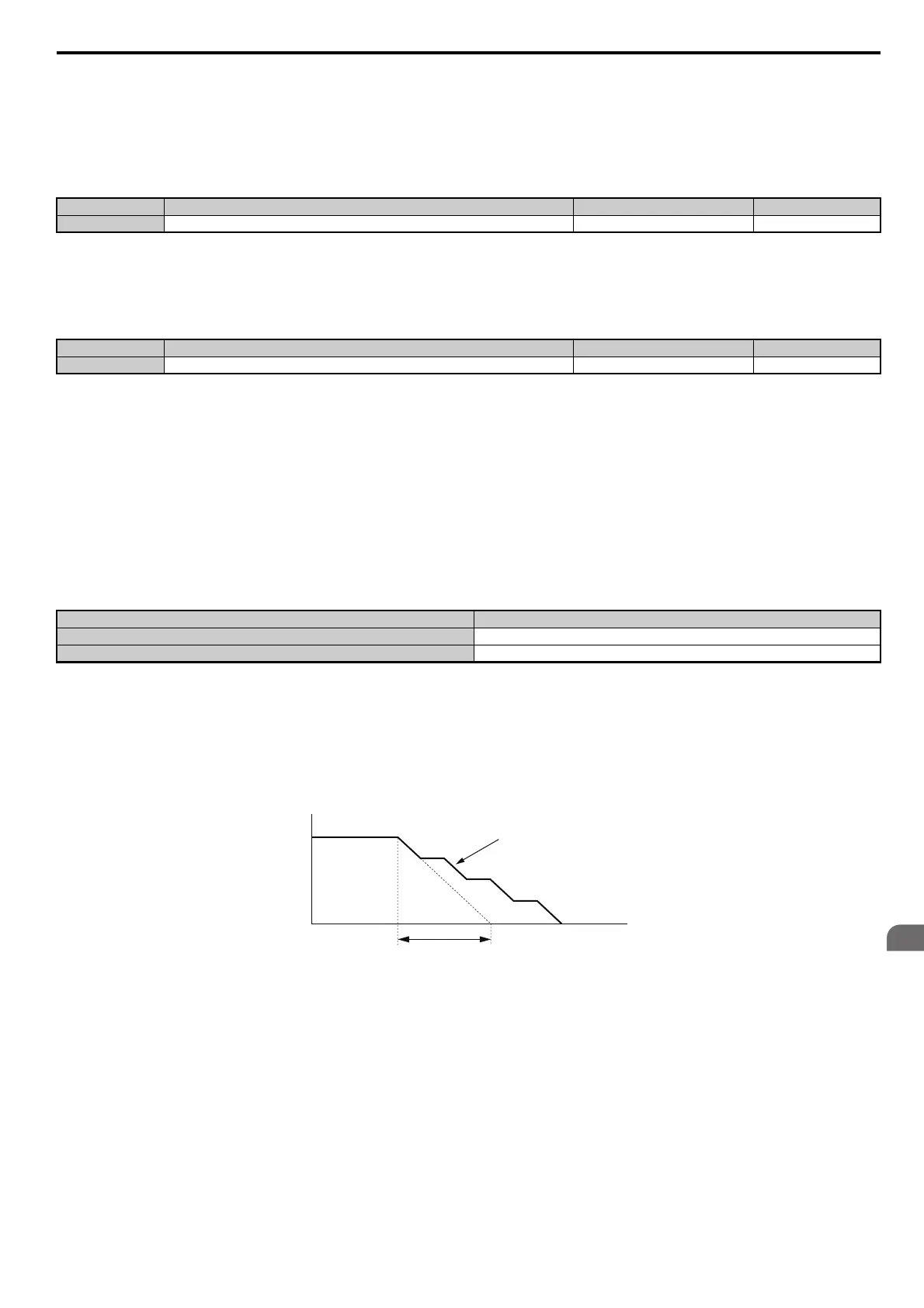
Figure 5.75 illustrates the function of Stall Prevention during deceleration.
Figure 5.75
Figure 5.75 Stall Prevention During Deceleration
Setting 2: Intelligent Stall Prevention
With this setting, the drive adjusts the deceleration rate so that the DC bus voltage is kept at the level set in parameter L3-
17. This way the shortest possible deceleration time is achieved while the motor is protected from stalling. The
deceleration time that has been selected is disregarded, but the achievable deceleration time cannot be smaller than 1/10
of the set deceleration time.
This function uses the following parameters for adjusting the deceleration rate:
• DC bus voltage gain (L3-20)
• Deceleration rate calculations gain (L3-21)
• Inertia calculations for motor acceleration time (L3-24)
• Load inertia ratio (L3-25)
No. Name Setting Range Default
L3-22 Deceleration Time at Stall Prevention During Acceleration 0.0 to 6000.0 s 0.0 s
No.
<1> Settings 4 and 5 are not available in OLV/PM.
Name Setting Range Default
L3-04 Stall Prevention Selection During Deceleration 0 to 2, 4, 5 <1> 1
Drive Input Voltage Stall Prevention Level during Deceleration
200 V Class 377 Vdc
400 V Class 754 Vdc
Output Frequency
Deceleration characteristics
when Stall Prevention was
triggered during deceleration
Time
specified deceleration time
SIEP_C710616_35.book 223 ページ 2015年11月30日 月曜日 午後2時2分