B.3 Parameter Table
YASKAWA ELECTRIC SIEP C710616 35D YASKAWA AC Drive E1000 Technical Manual 393
■ U2: Fault Trace
U1-14
(4FH)
Terminal A2 Input Level
Displays the signal level to analog input terminal A2.
10 V: 100% 0.1% –
U1-15
(50H)
Terminal A3 Input Level
Displays the signal level to analog input terminal A3.
10 V: 100% 0.1% –
U1-16
(53H)
Output Frequency after Soft
Starter
Displays output frequency with ramp time and S-curves. Units determined by o1-03.
10 V: Max frequency 0.01 Hz –
U1-18
(61H)
oPE Fault Parameter
Displays the parameter number that caused the oPE or Err (EEPROM write error) error.
No signal output
available
––
U1-19
(66H)
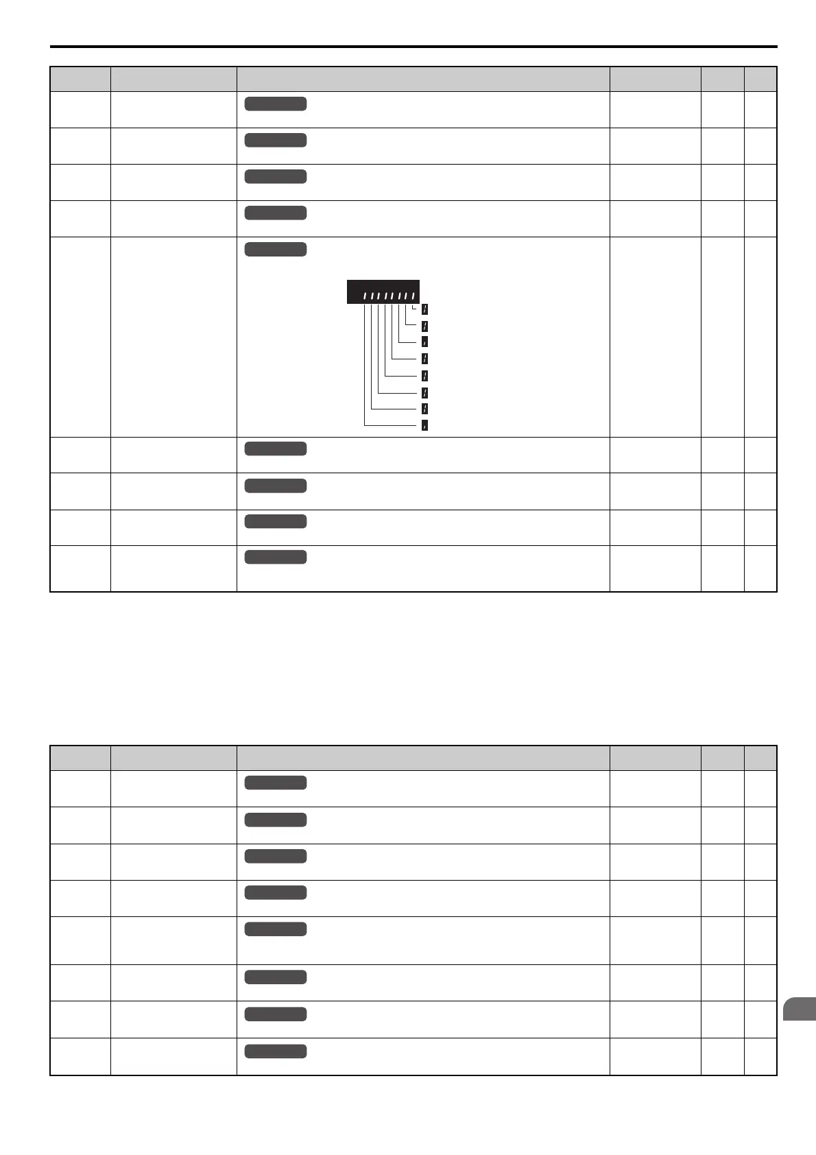
MEMOBUS/Modbus Error
Code
Displays the contents of a MEMOBUS/Modbus error.
No signal output
available
––
U1-24
(7DH)
Input Pulse Monitor
Displays the frequency to pulse train input terminal RP.
Determined by H6-02 1 Hz –
U1-25
(4DH)
Software Number (Flash)
FLASH ID
No signal output
available
––
U1-26
(5BH)
Software No. (ROM)
ROM ID
No signal output
available
––
U1-29
(7AAH)
Software No. (PWM)
PWM ID
Note: This parameter is displayed in models CIMR-E4A0930 and 4A1200.
No signal output
available
––
<18> Values shown here are for 200 V class drives. Double the value when using a 400 V class drive.
<19> This value's number of decimal places depends on the drive model. The value will have two decimal places (0.01 A) if the drive model is
CIMR-E2A0004 to 2A0040, 4A0002 to 4A0023 and one decimal place (0.1 A) if the drive model is CIMR-E2A0056 to 2A0415, 4A0031
to 4A1200.
<22> Drives with a maximum output up to 11 kW will display this value in units of 0.01 kW (two decimal places). Drives with a maximum output
greater than 11 kW will display this value in units of 0.1 kW (one decimal place). Refer to Model Number and Nameplate Check on page 29
for details.
<50> When reading the value of this monitor via MEMOBUS/Modbus a value of 8192 is equal to 100% of the drive rated output current.
No. (Addr.) Name Description
Analog Output
Level
Unit Page
U2-01
(80H)
Current Fault
Displays the current fault.
No signal output
available
––
U2-02
(81H)
Previous Fault
Displays the previous fault.
No signal output
available
––
U2-03
(82H)
Frequency Reference at
Previous Fault
Displays the frequency reference at the previous fault.
No signal output
available
0.01 Hz –
U2-04
(83H)
Output Frequency at Previous
Fault
Displays the output frequency at the previous fault.
No signal output
available
0.01 Hz –
U2-05
(84H)
Output Current at Previous
Fault
Displays the output current at the previous fault.
Note: The unit is expressed in 1 A for models CIMR-E4A0930 and 4A1200.
No signal output
available
<19> <50> –
U2-07
(86H)
Output Voltage at Previous
Fault
Displays the output voltage at the previous fault.
No signal output
available
0.1 Vac –
U2-08
(87H)
DC Bus Voltage at Previous
Fault
Displays the DC bus voltage at the previous fault.
No signal output
available
1 Vdc –
U2-09
(88H)
Output Power at Previous
Fault
Displays the output power at the previous fault.
No signal output
available
0.1 kW –
No. (Addr.) Name Description
Analog Output
Level
Unit Page
All Modes
All Modes
All Modes
All Modes
All Modes
CRC Error
Data Length Error
Not Used
Parity Error
Overrun Error
Framing Error
Timed Out
Not Used
All Modes
All Modes
All Modes
All Modes
All Modes
All Modes
All Modes
All Modes
All Modes
All Modes
All Modes
All Modes
SIEP_C710616_35.book 393 ページ 2015年11月30日 月曜日 午後2時2分