6.4 Fault Detection
268 YASKAWA ELECTRIC SIEP C710616 35D YASKAWA AC Drive E1000 Technical Manual
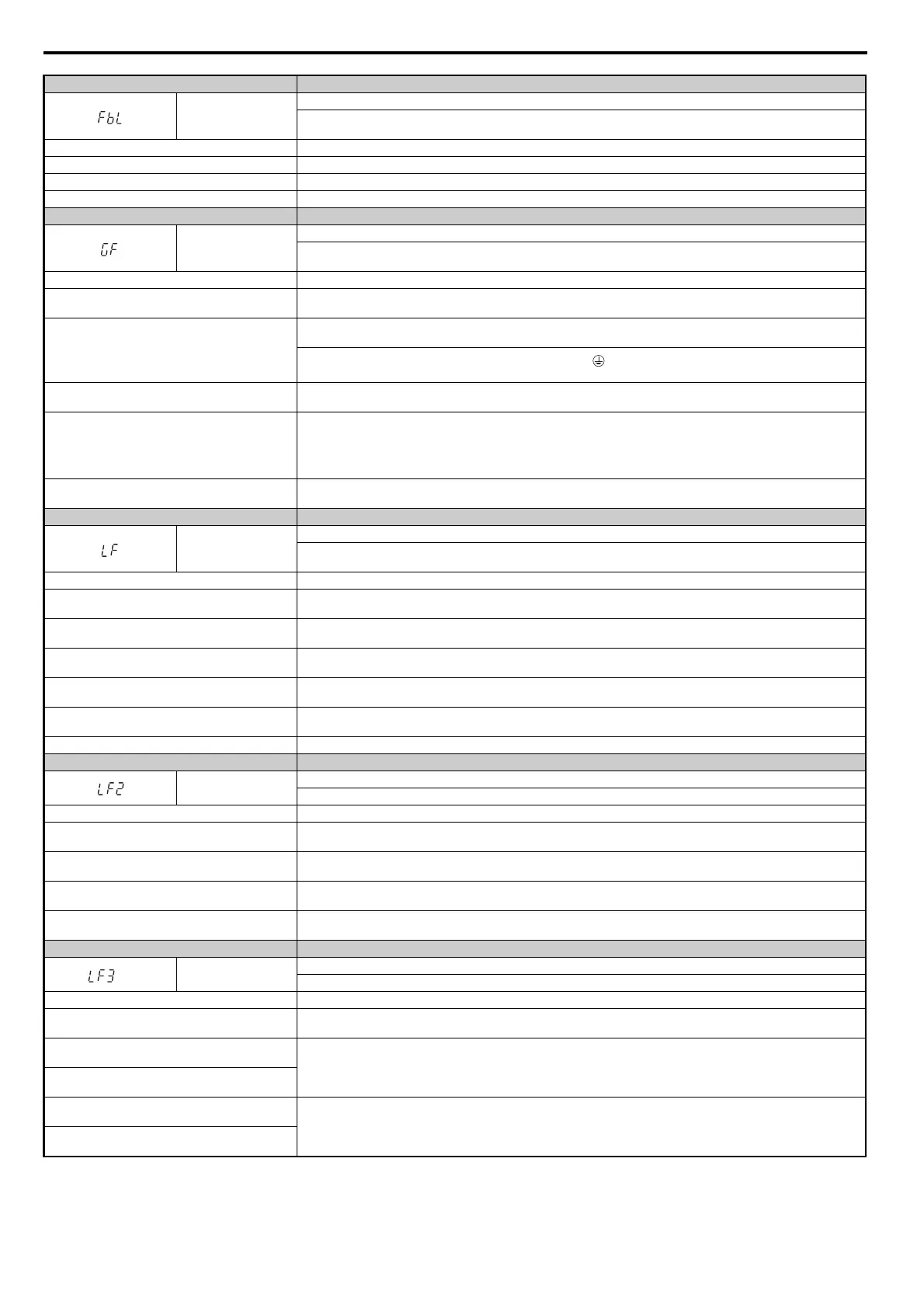
Digital Operator Display Fault Name
FbL
PI Feedback Loss
This fault occurs when PI feedback loss detection is programmed to trigger a fault (b5-12 = 2) and the PI feedback level is below
the detection level set to b5-13 for longer than the time set to b5-14.
Cause Possible Solution
Parameters are not set appropriately. Check the settings of parameters b5-13 and b5-14.
Wiring for PI feedback is incorrect. Correct the wiring.
There is a problem with the feedback sensor. Check the sensor on the controller side. If damaged, replace the sensor.
Digital Operator Display Fault Name
GF
Ground Fault
• A current short to ground exceeded 50% of rated current on the output side of the drive.
• Setting L8-09 to 1 enables ground fault detection.
Cause Possible Solution
Motor insulation is damaged.
• Check the insulation resistance of the motor.
• Replace the motor.
A damaged motor cable is creating a short circuit.
• Check the motor cable.
• Remove the short circuit and turn the power back on.
• Check the resistance between the cable and the ground terminal .
• Replace the cable.
The leakage current at the drive output is too high.
• Reduce the carrier frequency.
• Reduce the amount of stray capacitance.
The drive started to run during a current offset fault or
while coasting to a stop.
• The value set exceeds the allowable setting range while the drive automatically adjusts the current offset (this happens only
when attempting to restart a PM motor that is coasting to stop).
• Enable Speed Search at start (b3-01 = 1).
• Perform Speed Search 1 or 2 (H1- = 61 or 62) via one of the external terminals.
Note: Speed Search 1 and 2 are the same when using PM OLV.
Hardware problem.
Replace either the control board or the entire drive. For instructions on replacing the control board, contact Yaskawa or your
nearest sales representative.
Digital Operator Display Fault Name
LF
Output Phase Loss
• Phase loss on the output side of the drive.
• Phase Loss Detection is enabled when L8-07 is set to 1 or 2.
Cause Possible Solution
The output cable is disconnected.
• Check for wiring errors and ensure the output cable is connected properly.
• Correct the wiring.
The motor winding is damaged.
• Check the resistance between motor lines.
• Replace the motor if the winding is damaged.
The output terminal is loose.
• Apply the tightening torque specified in this manual to fasten the terminals. Refer to Wire Size and Torque Specifications on
page 82.
The rated current of the motor being used is less than 5%
of the drive rated current.
Check the drive and motor capacities.
An output transistor is damaged.
Replace either the control board or the entire drive. For instructions on replacing the control board, contact Yaskawa or your
nearest sales representative.
A single-phase motor is being used. The drive cannot operate a single phase motor.
Digital Operator Display Fault Name
LF2
Output current imbalance (detected when L8-29 = 1)
One or more of the phases in the output current is lost.
Cause Possible Solution
Phase loss has occurred on the output side of the drive.
• Check for faulty wiring or poor connections on the output side of the drive.
• Correct the wiring.
Terminal wires on the output side of the drive are loose.
Apply the tightening torque specified in this manual to fasten the terminals. Refer to Wire Size and Torque Specifications on
page 82.
The output circuit is damaged.
Replace either the control board or the entire drive. For instructions on replacing the control board, contact Yaskawa or your
nearest sales representative.
Motor impedance or motor phases are uneven.
• Measure the line-to-line resistance for each motor phase. Ensure all values are the same.
• Replace the motor.
Digital Operator Display Fault Name
<2>
LF3
Power Unit Output Phase Loss 3
Phase loss occurred on the output side (L8-78 is enabled).
Cause Possible Solution
The gate drive board in the power unit is damaged.
Cycle the power supply. Refer to Diagnosing and Resetting Faults on page 287 for instructions. If the fault continues to occur,
replace the gate drive board or the drive.
The current detection circuit in the power unit is
damaged.
Check for any incorrect wiring.
Correct any wiring mistakes.
Cable to the current detection circuit in the power unit is
not connected properly.
Cable between the output reactor and the power unit is
not connected.
Contact Yaskawa or your nearest sales representative for instructions.
Cable between the output reactor and the power unit is
loose.
SIEP_C710616_35.book 268 ページ 2015年11月30日 月曜日 午後2時2分