7.4 Cooling Fan and Circulation Fan
Periodic Inspection &
Maintenance
7
YASKAWA ELECTRIC SIEP C710616 35D YASKAWA AC Drive E1000 Technical Manual 321
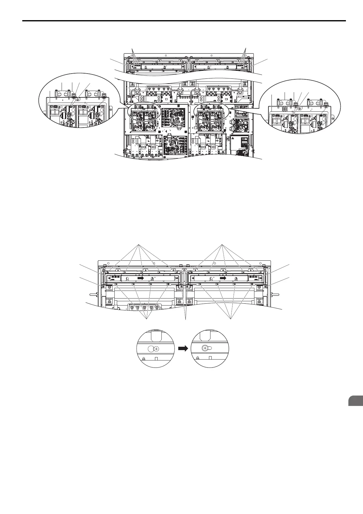
2. Remove the connectors for the cooling fan relay and the circuit board cooling fan.
Figure 7.41
Figure 7.41 Component Names: 4A0930 and 4A1200
3. Loosen screw A (4 count) and screw B (18 count), and slide the panel to the right.
Note: The fan unit can be removed by loosening these screws; they do not need to be removed.
Figure 7.42
Figure 7.42 Removing the Fan Unit: 4A0930 and 4A1200
A – Fan Unit (L) F – Circuit Cooling Fan Case
B – Fan Relay Connector (L) G – Hook
C – Fan Unit (R) H – Circuit Board Cooling Fan
Connector
D – Fan Relay Connector (R) I – Circuit Board Cooling Fan Cable
E – Circuit Board Cooling Fan
A
B
C
D
IE
F
HG
E
F
IGH
Circuit board cooling fan (L)
Circuit board cooling fan (R)
Screw B Screw A Screw B
Screw B Screw B
Screw A
Slide Panel
Screw A
Slide Panel
SIEP_C710616_35.book 321 ページ 2015年11月30日 月曜日 午後2時2分