4.4
I/O Module (Optional) Connections
4-51
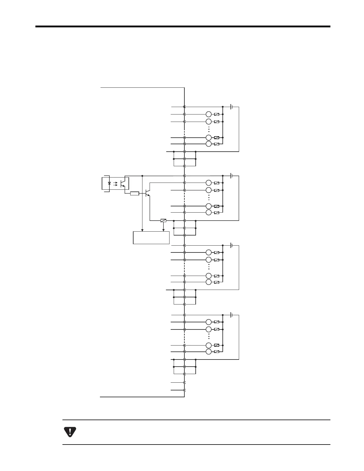
( 6 ) DO-01 Module Connector Connection Examples
■
CN1 Connector Connection Example
The pins No. 6, 26, and 31, the pins 12, 32, and 37, the pins 18, 38, and 43, and the pins No. 24,
44, and 49 are internally connected. Connect them externally as well.
7
8
33
11
36
13
12
14
39
17
42
18
19
20
45
23
48
24
25
50
CN1 connector
pin No.
1
2
27
5
30
6
31
26
Output 1
+-
L
L
L
L
Output 0
Output 7
Output 6
Output 9
+-
24 VDC
L
L
L
L
Output 8
Output 15
Output 14
Output 17
+-
24 VDC
L
L
L
L
Output 16
Output 23
Output 22
Output 25
+-
24 VDC
L
L
L
L
Output 24
Output 31
Output 30
Photocoupler
JAPMC-DO2300
Fuse
Fuse
24 VDC
R
37
32
43
38
49
44
Fuse blowout
detection circuit
A fuse is inserted in the output common line of the DO-01 Module for circuit protection. However, the fuse
may not be blown out in the cases such as layer shorts in outputs. To ensure the circuit protection, provide a
protective element such as fuse in each output as shown in the above diagram.

 Loading...


