Master Table of Contents - 16 CELL-DYN 3000 System Operator’s Manual
9140240E — May 1995
Figure 9.11: Data Station Rear Panel . . . . . . . . . . . . . . . . . . . . . .9-31
Figure 9.12: Special Protocols: Extended Auto-Clean Screen . . .9-33
Figure 9.13: Transducer Assembly — Levers Closed . . . . . . . . . .9-35
Figure 9.14: Transducer Assembly and Aperture Plate . . . . . . . . .9-37
Figure 9.15: The HGB Mixing Chamber, HGB Flow Cell
and Solenoid 14 . . . . . . . . . . . . . . . . . . . . . . . . . . . . .9-39
Figure 9.16: Closed Sampler Module . . . . . . . . . . . . . . . . . . . . . .9-43
Figure 10.1: First Diagnostics Menu Screen . . . . . . . . . . . . . . . . .10-4
Figure 10.2: Operator Correctable Fault Report Screen . . . . . . . .10-5
Figure 10.3: Fatal Fault Report Screen . . . . . . . . . . . . . . . . . . . . .10-6
Figure 10.4: Fault Report – No Fault Pending Screen . . . . . . . . .10-7
Figure 10.5: Count Rate Summary Screen . . . . . . . . . . . . . . . . . .10-8
Figure 10.6: WBC Count Rate Data . . . . . . . . . . . . . . . . . . . . . . .10-9
Figure 10.7: WBC Count Rate Graph . . . . . . . . . . . . . . . . . . . . .10-10
Figure 10.8: Raw Data Summary Screen . . . . . . . . . . . . . . . . . .10-11
Figure 10.9: Second Diagnostics Menu Screen . . . . . . . . . . . . . .10-12
Figure 10.10: Pump Operation Screen . . . . . . . . . . . . . . . . . . . . .10-13
Figure 10.11: Pump Operation Screen — Vacuum ON . . . . . . . .10-14
Figure 10.12: Inhibit Pumps Screen . . . . . . . . . . . . . . . . . . . . . . .10-15
Figure 10.13: Vacuum Test Screen . . . . . . . . . . . . . . . . . . . . . . . .10-16
Figure 10.14: Third Diagnostics Menu Screen . . . . . . . . . . . . . . .10-17
Figure 10.15: Voltage Readings Screen . . . . . . . . . . . . . . . . . . . .10-18
Figure 10.16: Fourth Diagnostics Menu Screen . . . . . . . . . . . . . .10-19
Figure 10.17: Fifth Diagnostics Menu Screen
(CELL-DYN 3000SL) . . . . . . . . . . . . . . . . . . . . . .10-20
Figure 10.18: Auto-Sampler Version Screen . . . . . . . . . . . . . . . .10-21
Figure 10.19: Serial Test Screen . . . . . . . . . . . . . . . . . . . . . . . . . .10-22
Figure 10.20: Serial Test Transmit Message Screen . . . . . . . . . . .10-23
Figure 10.21: Open Sample Aspiration Probe . . . . . . . . . . . . . . . .10-31
Figure 10.22: Sample Loader Vent/Aspiration
Needle Assembly . . . . . . . . . . . . . . . . . . . . . . . . . . .10-34
Figure 11.1: OKIDATA® MICROLINE® Printer . . . . . . . . . . . .11-3
Figure 11.2: Printer Carriage Shaft and Platen . . . . . . . . . . . . . . .11-5
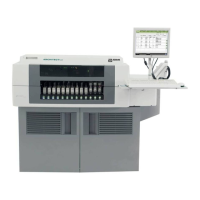
Figure 12.1: Analyzer with Sample Loader . . . . . . . . . . . . . . . . . .12-1
Figure 12.2: Rack Movement . . . . . . . . . . . . . . . . . . . . . . . . . . . .12-2
Figure 12.3: Tube Labeling Requirements . . . . . . . . . . . . . . . . . .12-3