Gen II User Manual
7-37 – Main Rotor Track & Balance Chapter 7 Revision 3.00, Apr 2020
7.7.1.1. – Regular Main Rotor
Chart Setup
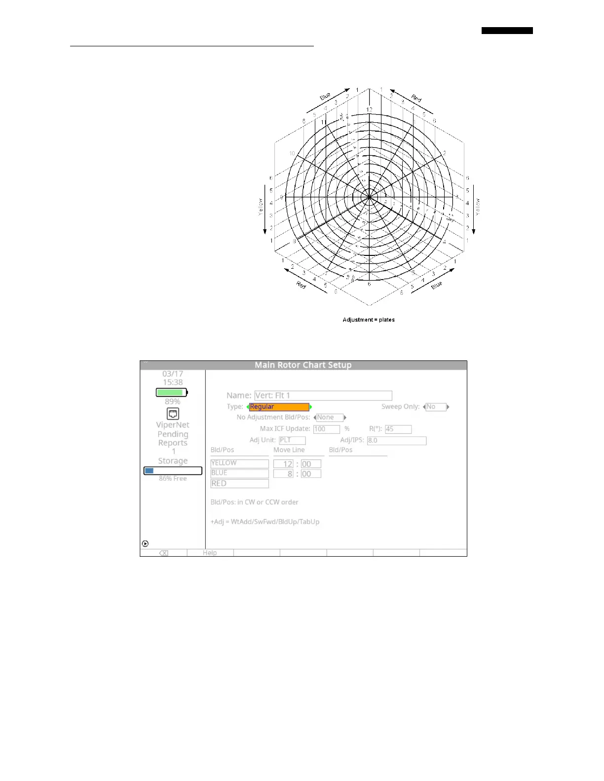
The main rotor balance chart shown
to the right depicts three weight
positions, Red, Yellow, and Blue.
The move line for each position has
been indicated with an arrow, the
type of adjustment given below the
chart is “Plates”. The ICF is
approximately 7 plates per 1.0 IPS.
This chart meets all criteria to place
it in the “Regular” chart type
category. All weight positions have
the same ICF and type of
adjustment, and all move lines are
equally spaced around the chart.
Using this chart, follow the example
below to properly define a
“Regular” main rotor chart setup in the analyzer.
Name: The name of the chart will be automatically inserted from the “Main Rotor
Condition Setup” screen and is not editable.
Chart Type: Using the [] or [] key, select the chart type. For this example, the chart type is
“Regular”.
Sweep Only: This field is used when defining a chart that utilizes blade sweep only as a means of
adjustment. If the chart you are defining uses only sweep moves, select “YES”
using either the [] or [] keys. Otherwise, leave this field set to “NO”.
 Loading...