Gen II User Manual
2-7 – Analyzer Description Chapter 2 Revision 2.1, April
The Modified Tooth setting is a variable configuration (low tooth, high tooth, offset tooth, or
missing tooth) monopole input. The odd tooth can be used as a once-per-revolution reference for
balancing and speed indication purposes.
2.3.1.3. – AUX/COMM Port
The “AUX/COMM” or Auxiliary and Communications port is a six-pin MS type male
connector. This port is used to connect an ACES Systems’ Model 550 TraX
TM
to the analyzer for
helicopter main rotor blade tracking.
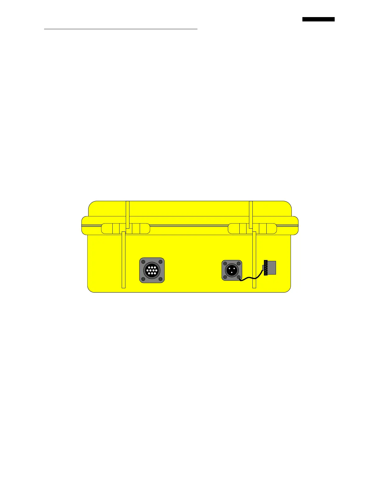
2.3.2. – Side Panel
Two additional input /output ports are provided on the left panel of the analyzer. They are the 18-
28V DC IN and STRB/JEDA/ACCY (Viper II) or STRB/ACCY (Cobra II – not pictured) ports.
STRB / JEDA / ACCY
18-28V DC IN
2.3.2.1. - STRB / JEDA / ACCY Port (Viper II) or STRB / ACCY Port (Cobra II – not
pictured)
This port is used for connection of a current and future accessories designed to work with the
Gen II analyzers.
Both Gen II analyzers support the use of a strobe light for manual, visual tracking of rotor or
propeller blades. The analyzer provides a trigger for the strobe through this port. Power (28V
DC) for the strobe must be provided from outside the analyzer, usually from a ship’s power
source. The strobe and necessary cables are available as optional equipment from ACES
Systems.
 Loading...