Chapter 8
Tail Rotor Balance
(Revision 3.00, April 2020)
This section is intended to familiarize you with the various electronic chart forms and setup
screens used with the Gen II Analyzer, first by looking at each of the chart forms found in the
tail rotor section, then by using these forms to create an actual setup.
8.1. – Tail Rotor Setup
The following paragraphs illustrate each of the screens necessary to define and store a tail
rotor setup.
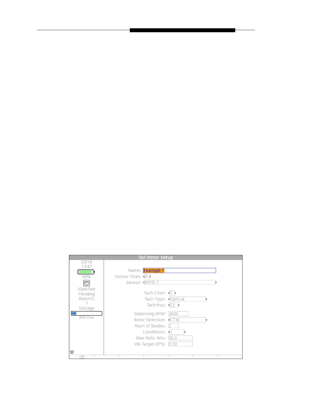
8.1.1. – Tail Rotor Setup Screen
Use the following screen capture and polar chart to follow the steps below to complete the
tail rotor setup screen for “Example 1” as shown below.
 Loading...