Gen II User Manual
8-13 – Tail Rotor Balance Chapter 8 Revision 3.00, April 2020
The “Connect Sensors” banner screen will be displayed next. Messages that appear on this
screen prompt you to perform the physical installation and connection of the tachometer and
vibration sensors to the input ports you specified in the applicable setup.
You must use the vibration sensor installation location as specified by the applicable
polar chart. The orientation of the sensor is key to the accuracy of the chart. If the
sensor is installed in a direction other than that specified, the phase (clock) angle will
be incorrect and any solution will not be accurate.
Tach Power need not be “ON” before leaving this screen. The option simply exists for
installing and checking alignment of the reflective tape and PhotoTach. When completed,
press [OK].
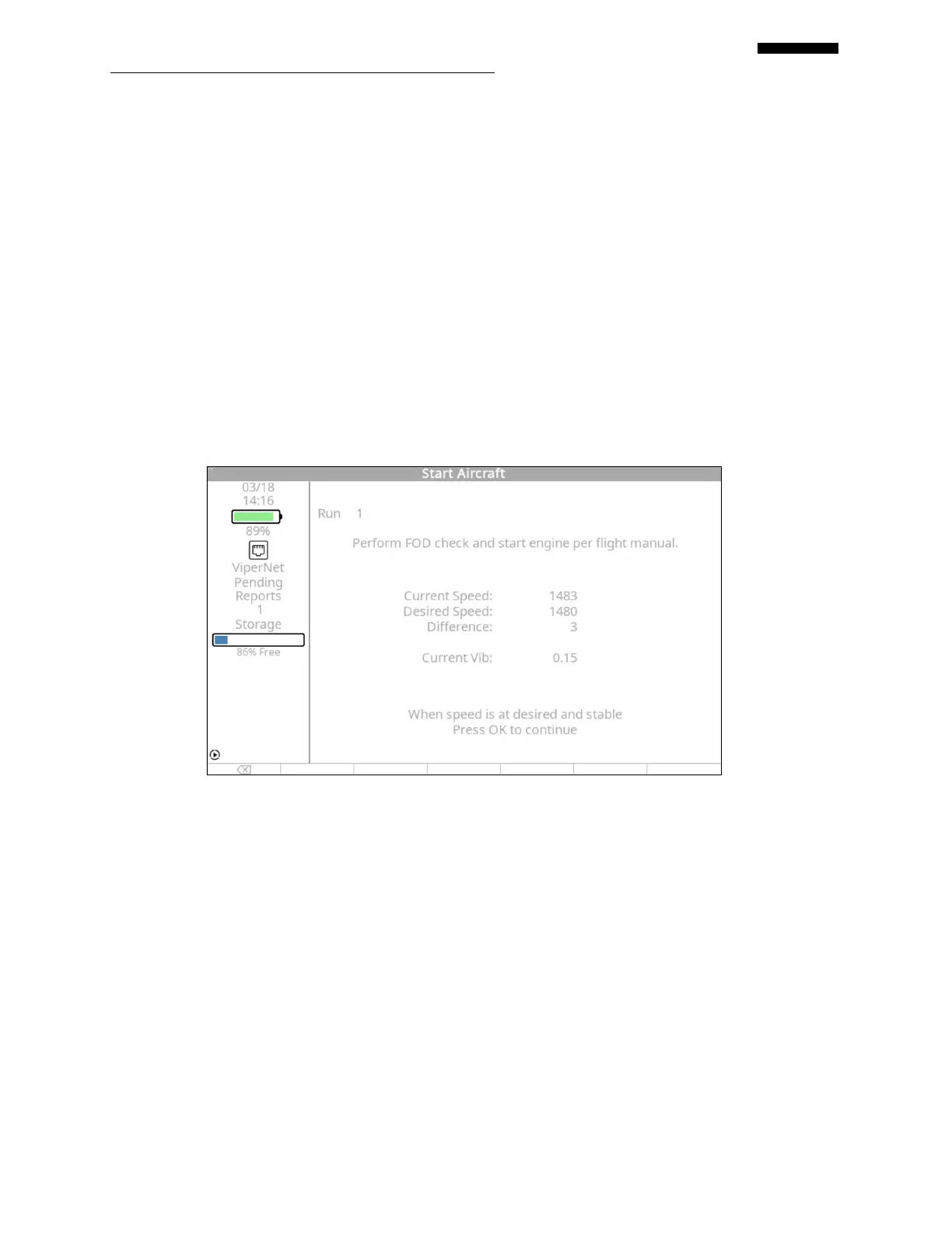
8.3.5. – Start Aircraft
The “Start Aircraft” screen appears. The current run number is displayed at the top of the
screen, followed by both the current and desired speed in RPM, difference between the
speeds and the current vibration reading. Once the current speed matches the desired speed,
press [OK] to begin data acquisition.
 Loading...