Gen II User Manual
4-2 – Propeller Balance Chapter 4 Revision 2.2, Apr 2020
Propeller Balancing Kit
The propeller balancing kit contains all the necessary items to complete a single-engine, single-
plane propeller balance. If your requirements are multiple-plane balance on a single-engine or
multiple-engine balancing, additional equipment will be required. The items in the propeller
balancing kit are described below.
Manual, ACES Systems Guide to Propeller Balancing
The ACES Systems Guide to Propeller Balancing provides FAA-approved procedures and
practices for completing a propeller balance job in lieu of airframe or propeller manufacturers’
written instructions. The guide includes instructions on installing vibration sensors, photo
tachometers, and reflective tape. Information on selecting the proper trim weights, attaching trial
weights, attaching permanent weights, and other hints for simplifying the balance job are also
included. The guide does not provide information on using the analyzer. Review this user’s
manual for detailed information on the analyzer’s operation.
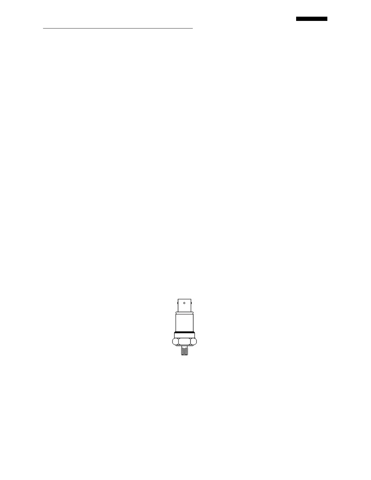
991D-1 Accelerometer
Although the Gen II analyzers will support a full range of vibration sensors, the 991D-1
accelerometer (see the illustration below) was selected as the standard for use with the propeller
balance kit due to its rugged construction, accuracy, cost, and range of operation. A single sensor
is supplied with the propeller balancing kit. Additional sensors may be purchased separately.
The output of the 991D-1 accelerometer is 20 mV per g. The 991D-1 is pre-programmed in the
analyzer’s sensor setup list. The operating temperature range is -50 to + 120 degrees C. The
three-pin connector is a MIL-C -26482, and the mating connector is a Bendix PT06-8-3S. The
mounting stud is 1/4 x 28. Although the sensor is rugged, it can be damaged when dropped on
hard surfaces. Use care when installing the sensor, as you would with other electronic
components.
991D-1 Sensor Cable
The 991D -1 sensor cable, shown below, is a 25-foot (50-foot optional) shielded and Teflon-
coated four-conductor cable. The three-pin MS female connector on one end of the cable mates
to the 991D -1 sensor. The six-pin MS male connector mates to one of the four (CHANNEL A,
B, C, or D) vibration-input ports available on the analyzer. Contact ACES Systems for other
sensor, cable, or adapter options.
 Loading...