Gen II User Manual
7-36 – Main Rotor Track & Balance Chapter 7 Revision 3.00, Apr 2020
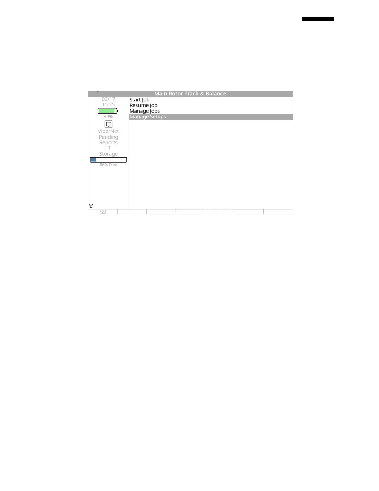
7.6. – Manage Setups
The features in this section are common among all jobs. Because of this, they are contained in
Chapter 3, “Using the Gen II Analyzer”.
7.7. – Analyzer Chart Forms
Just as in the case with polar balance charts, there are two types of analyzer chart “forms” used
with the Analyzer and one tracking influence setup screen. The chart forms are also categorized
as either “Regular” or “Irregular”. The selection of setup type is made within the chart form itself
by using either the [] or [] keys to toggle between “Regular” and “Irregular” in the “Chart
Type” field, then pressing the [] key to move to the next field. The remaining fields in the
screen will automatically change if necessary. The tracking influence setup screen is separate
from the chart forms and allows entry of the amount of adjustment required to move the blade a
specified distance. The paragraphs below describe these forms in detail.
7.7.1. – Regular Chart Forms
A “Regular” chart is one that has all weight positions spaced equally around the chart, all
adjustments are of the same type, and all adjustments carry the same ICF. The next paragraphs
detail the process for defining both a main rotor and tail rotor “Regular” chart setup. There are
slight differences between the two functions that will be noted in the text.
 Loading...