Gen II User Manual
9-18 – Transient Balance Chapter 9 Revision 2.10, Apr 2020
hole number and an <-X->. The X symbolizes that a Detail Weight is located in this
hole and it is not available for trim balancing.
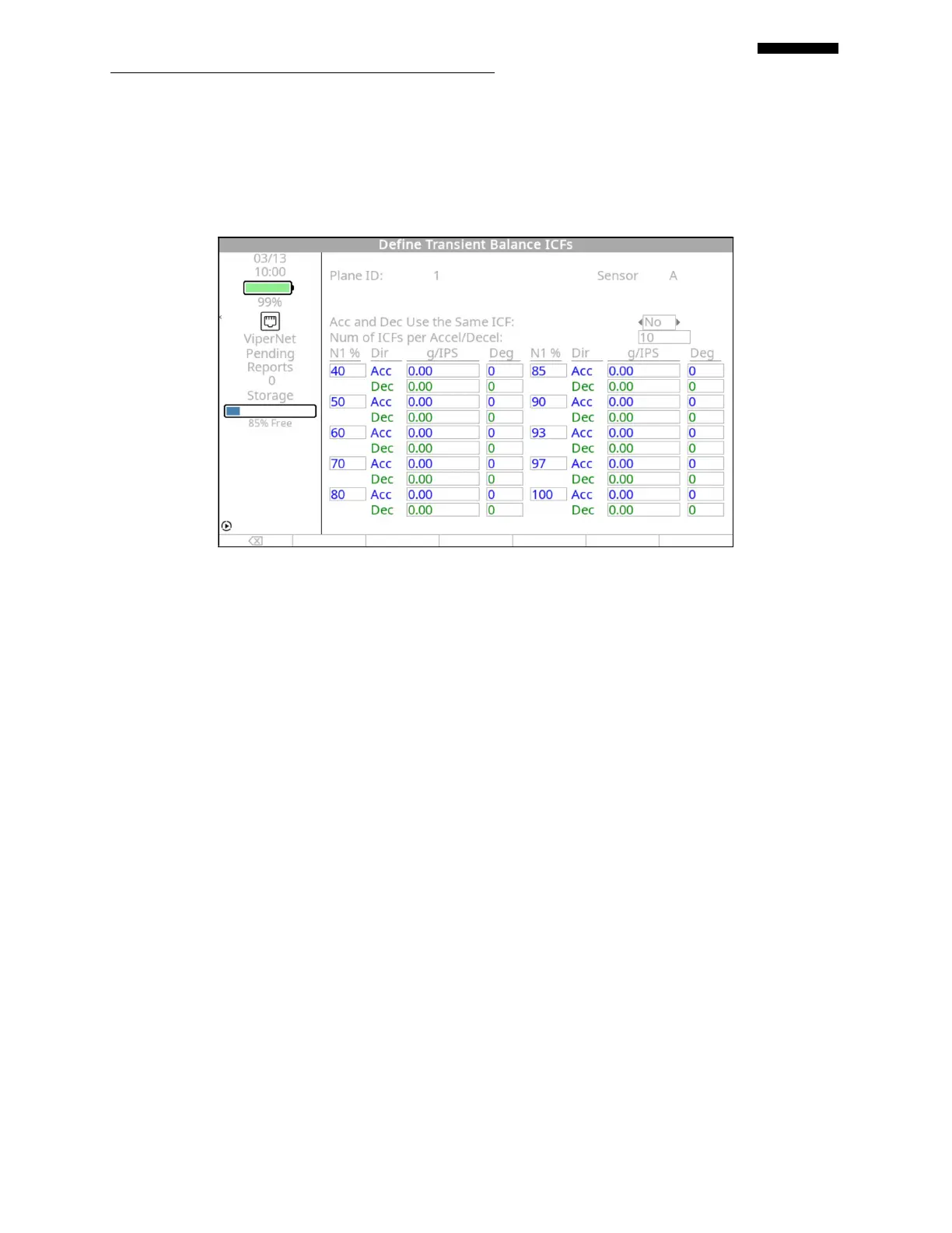
9.1.7. – Define Transient Balance ICFs Screen
9.1.7.1. The “Plane ID:” field displays the identifying number for the balance plane being
configured.
9.1.7.2. The “All Planes Use the Same ICF:” field is only available if multiple balance
planes were defined in paragraphs 9.1.1.6 or 9.1.1.7 above. Use the [] to toggle the
YES / NO answer field to indicate if all balance planes should use the same influence
coefficient.
9.1.7.3. The “All Sensors Use the Same ICF:” field is only available if multiple sensors were
selected in paragraph 9.1.1.12 above. Use the [] to toggle the YES / NO answer
field to indicate if all sensors should use the same influence coefficient.
9.1.7.4. The “Acc and Dec Use the Same ICF:” field is only available if “Both” was selected
in the “Acquire on:” field in paragraph 9.1.3.2 above. Use the [] to toggle the YES /
NO answer field to indicate if acceleration and deceleration should use the same
influence coefficient.
9.1.7.5. The “Num of ICFs per Accel/Decel:” field is used to determine the number of ICFs
that will be configured in the lower half of the screen. You can enter any value from
“1” to “50”. If no known ICFs are available, leave this field at the default value of
“1”.
 Loading...