Gen II User Manual
8-8 – Tail Rotor Balance Chapter 8 Revision 3.00, April 2020
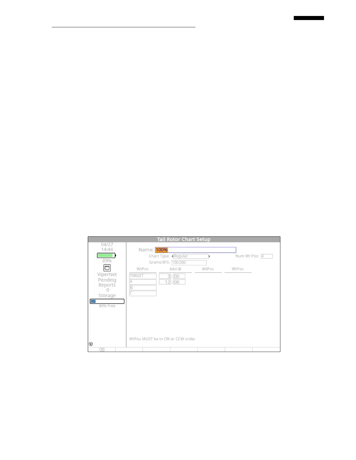
Press the [] key to enter the grams per IPS influence for the tail rotor. This example
uses “100.00” grams.
Press the [] key and enter the first weight position name as “TARGET”.
Press the [] key and enter the “Add @” move line for weight placement on the
“TARGET” blade as “12:00”.
Press the [] key and enter the second weight position name of “A”.
Press the [] key and enter the “Add @” move line for weight placement on the “A”
blade as “3:00”.
Press the [] key and enter the next blade name as “B”.
Press the [] key and enter the last blade name as “C”.
Press [OK] to continue to the next chart.
8.2.4. – Second Condition Tail Rotor Chart Setup Screen
The “Tail Rotor Chart Setup” screen for the second condition (100%) appears next. Using the
tail rotor polar chart, fill in the appropriate information as follows:
 Loading...