Gen II User Manual
8-9 – Tail Rotor Balance Chapter 8 Revision 3.00, April 2020
3
9
10
2
4
12
1
5
7
8
11
.
2
.
3
.4
.5
.6
.7
.8
.9
1
.0
"
I
P
S
"
1.
0
.
9
.
8
.
7
.
6
.
5
.
4
.
3
.
2
"I
PS
"
1.
0
.
9
.
8
.
7
.
6
.
5
.
4
.
3
.
2
"I
PS
"
6
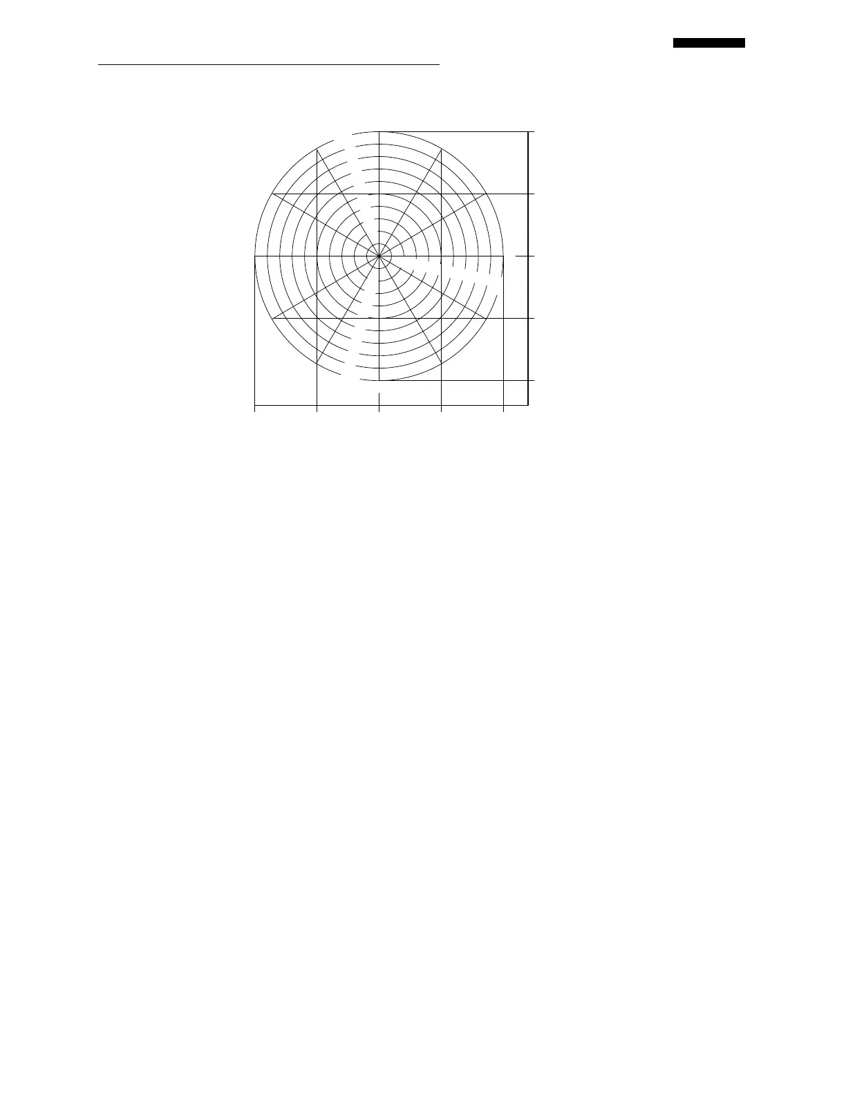
100% Balance Chart
100 50 0 50 100
100 50 0 50 100
+ B + Target
+ C + A
The name for the chart, “100%”, has already been inserted from the “Tail Rotor
Condition Setup” screen.
Press the [] key and select the chart type by pressing the [] key. The type of chart
for this example is “Regular”.
Press the [] key and enter the number of weight positions using the keypad. This
example uses 4 weight positions.
Press the [] key to enter the grams per IPS influence for the tail rotor. This example
uses “100.00” grams.
Press the [] key and enter the first weight position name as “TARGET”.
Press the [] key and enter the “Add @” move line for weight placement on the
“TARGET” blade as “3:00”.
Press the [] key and enter the second weight position name of “A”.
Press the [] key and enter the “Add @” move line for weight placement on the “A”
blade as “12:00”.
Press the [] key and enter the next blade name as “B”.
Press the [] key and enter the last blade name as “C”.
Press [OK] to continue to the next chart, if necessary.
 Loading...