Gen II User Manual
8-3 – Tail Rotor Balance Chapter 8 Revision 3.00, April 2020
choose “Dont Care” regardless of the actual direction of rotation of the tail rotor. For
further guidance contact Aces Support at support@acesystems.com.
Press the [] key to move to the “Number of Blades” field. Using the keypad, enter
the number of blades on the tail rotor. The maximum number of blades is 20.
Press the [] key to move to the “Conditions” field. Using the [] and [] keys,
enter the number of conditions. The maximum number of conditions is 3.
Press the [] key to proceed to the “Maximum Balance Weight” field. If there is a
published maximum amount of weight that may be used for balancing the tail rotor,
you may enter it in this block. This is the total amount of balance weight allowable,
not the limit of each balance position. If the Installed Weights for a single run is more
than the maximum allowed, the user will encounter a warning screen to notify him
that the maximum weight limit is being exceeded.
Press the [] key to proceed to the “Vib Target (IPS) field. Enter the Tail Rotor
Vibration Limit or Target from the applicable maintenance manual.
When finished with the main setup screen, press [OK].
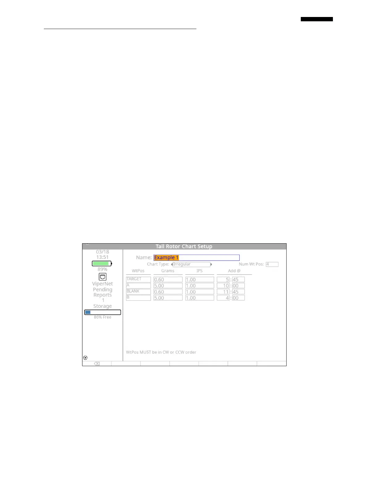
8.1.2. – Tail Rotor Chart Setup
The “Tail Rotor Chart Setup” screen appears next. Using the tail rotor polar chart
found in paragraph 8.1.1 titled “Tail Rotor Setup Screen”, fill in the appropriate
information as follows:
The name for the chart, “EXAMPLE 1”, has already been inserted from the first setup
screen.
 Loading...