Gen II User Manual
7-39 – Main Rotor Track & Balance Chapter 7 Revision 3.00, Apr 2020
NOTE
Blade position names must be entered sequentially in either clockwise or counter clockwise
order. It does not matter what direction is chosen.
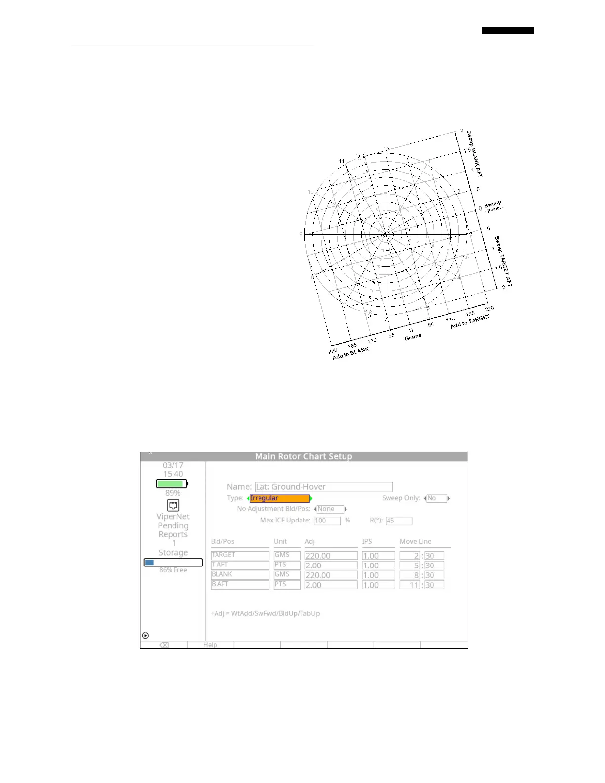
7.7.2. – Irregular Chart Forms
Any polar chart that does not fit the
“Regular” category must use the “Irregular”
chart form. The next paragraphs detail the
setup for both main rotor and tail rotor
“Irregular” chart setups.
7.7.2.1. – Irregular Main Rotor Chart
Setup
The main rotor balance chart shown to the
right presents two different types of
adjustments: the addition of weight to target
or blank, and sweeping either the target or
blank blade aft. The ICF is different for
each set of adjustments, 220 grams of weight per 1.0 IPS and 2 points of aft sweep per 1.0 IPS.
The move lines for these adjustments are equally spaced; however, because the ICF and
adjustment types are different, this chart must use the “Irregular” chart form. Using this chart,
follow the examples below to properly define an “Irregular” main rotor chart setup in the
analyzer.
Name: The name of the chart will be automatically inserted from the “Main Rotor Condition
Setup” screen and is not editable.
 Loading...