Gen II User Manual
2-5 – Analyzer Description Chapter 2 Revision 2.1, April
A single press of the [SPACE] key is used to enter a separating space in a text line. When
entering numeric values, two rapid presses of the key will enter a minus sign to change a positive
number to a negative value. When entering text, two rapid presses will enter a dash.
2.2. – Screen
The bright 7.0” WVGA transmissive color TFT display is how the analyzer communicates with
the user. The screen displays messages, menus, selection lists, graphic illustrations, and survey
plots. The display has an LED backlight with adjustable brightness and 800x480 resolution.
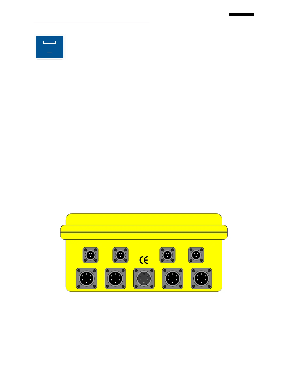
2.3. – Input and Output Ports
2.3.1. – Top Panel
The Viper II has nine input/output ports on the top panel of the analyzer, as shown in the figure
below: four “CHANNEL” (vibration channel) inputs, four “TACH” (tachometer) inputs, and one
“AUX/COMM” (auxiliary/communication) input/output port.
CHANNEL D
CHANNEL C
AUX/COMM
CHANNEL A
CHANNEL B
TACH 4
TACH 3
TACH 2
TACH 1
 Loading...