Gen II User Manual
2-6 – Analyzer Description Chapter 2 Revision 2.1, April
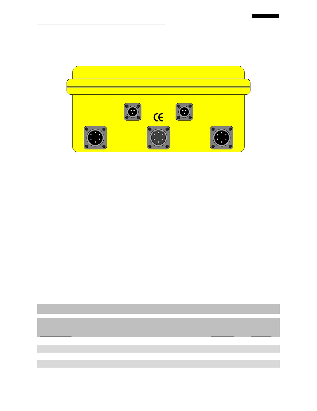
The Cobra II has five input/output ports on the top end panel of the analyzer, as shown in the
figure below: two “CHANNEL” (vibration channel) inputs, two “TACH” (tachometer) inputs,
and one “AUX/COMM” (auxiliary/communication) input/output port.
AUX/COMM
CHANNEL A
CHANNEL B
TACH 2
TACH 1
2.3.1.1. – CHANNEL Ports
The vibration CHANNEL inputs will accept acceleration, velocity, or displacement sensor
signals. All vibration CHANNEL inputs are six-pin MS socket connectors. Any of the channels
may be specified in the SETUP function as the input for a single plane balance job. The six-pin
connector enables the analyzer to provide sensor power as required to the sensor being used.
2.3.1.2. – TACH Ports
The “TACH” inputs are three-pin female receptacle connectors. Both Gen II analyzers will
accept either a raw tachometer speed reference signal or a Transistor-Transistor Logic (TTL)
level speed signal. Power (+12V) is provided on one pin of the tachometer connector to power
optical speed sensors such as the Phototach or LASETACH
. The tach inputs available for each
analyzer version are outlined in the table below.
Table 2.1: ACES Gen II Analyzer Tach Inputs
Optical (Phototach or LaseTach)
Mag Pickup (Mag P/U)
Modified Tooth (Mod Tth)
Adjustable Tooth (Adj Tth)
 Loading...