Gen II User Manual
14-10 – Vibration Spectrum Survey Chapter 14 Revision 4.10, Apr 2020
14.1.1.4.2. Use the [] and [] keys to navigate the screen and input or select units using the keypad
or the [] and [] keys respectively.
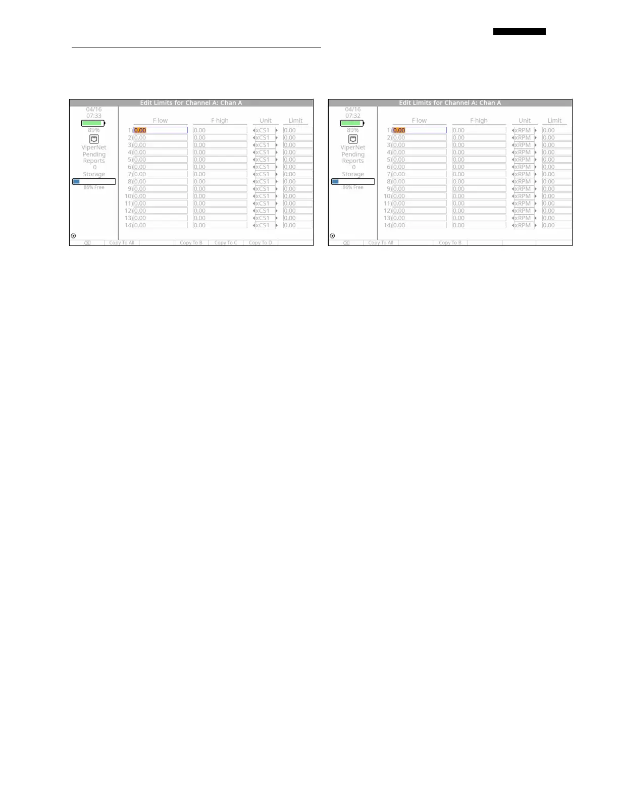
14.1.1.4.3. The “Edit Limits for Channel X” banner screen, where X represents the input channel
letter A, B, C, or D, shown above, will be displayed.
14.1.1.4.4. Use the keypad to enter the lowest frequency of interest, “F-low”. If “Unit” is set to
“RPM” or “Hz”, this value will define the lowest frequency in a fixed range. The Viper II
provides the additional selections of xCS1 through xCS4. If “Unit” is set to one of these,
this value is multiplied by that component speed (configured in paragraph 14.1.1.3
above) and defines the lowest frequency variance where you will monitor the component
speed.
14.1.1.4.5. Use the keypad to enter the highest frequency of interest, “F-high”. If “Unit” is set to
“RPM” or “Hz”, this value will define the highest frequency in a fixed range. The Viper
II provides the additional selections of xCS1 through xCS4. If “Unit” is set to one of
these, this value is multiplied by that component speed (configured in paragraph 14.1.1.3
above) and defines the highest frequency variance where you will monitor the component
speed.
14.1.1.4.6. Move to the next column “Unit” and use the [] and [] keys to select the frequency
unit. This selection will determine the frequency unit where lines will be drawn on the
spectra relative to the x (frequency) axis specified in paragraph 14.1.1.1.2 above. The
available units are: xRPM used to enter a limit relative to a specific RPM range, or xHz
used to enter a limit relative to a specific Hz range. The Viper II provides additional units
of xCS1, xCS2, xCS3, and xCS4 (CS is an abbreviation for Calculated Speed). These are
directly linked to the component speeds defined in paragraph 14.1.1.3 above.
14.1.1.4.7. Move to the “Limit” column and enter the amplitude limit for the bandwidth specified in
F-low and F-high of the same row. This limit will be displayed as a horizontal line
relative to the engineering units specified on the Spectra Setup screen in the “Vibration:”
 Loading...