Gen II User Manual
19-8 – Monitor Overall Chapter 19 Revision 2.10, Apr 2020
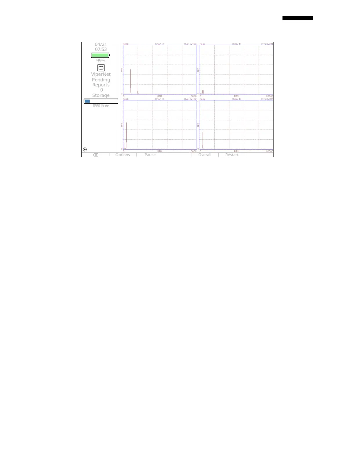
19.1.4.1. – Fields displayed when viewing Spectra
19.1.4.1.1. Modifier – Displayed in the upper left above the “Y” scale. This will display the modifier
for the affected channel entered in paragraph 19.1.1.7 above.
19.1.4.1.2. Channel description (Desc) – Centered at the top of the spectrum and is the description
for the affected channel entered in paragraph 19.1.1.11 above.
19.1.4.1.3. “Ovr:” – Displays the overall reading for the affected channel.
19.1.4.1.4. Minimum frequency – Displayed at the lower left corner of the spectrum and represents
the minimum frequency of the “X” scale as entered in paragraph 19.1.1.4.
19.1.4.1.5. Frequency unit – Centered at the bottom of the spectrum and is the frequency unit
selected in paragraph 19.1.1.3 above.
19.1.4.1.6. Maximum frequency – Displayed at the lower right corner of the spectrum and represents
the maximum frequency as entered in paragraph 19.1.1.5 above.
19.1.4.1.7. Full scale range – Displayed on top left corner of the spectrum and represents the
maximum range of the “Y” scale as entered in paragraph 19.1.1.8 above. The minimum
value for the “Y” scale will be “0”.
19.1.4.1.8. Sensor units – Centered on the left side of the spectrum and is the “Units” value selected
in paragraph 19.1.1.6 above.
 Loading...