Gen II User Manual
7-7 – Main Rotor Track & Balance Chapter 7 Revision 3.00, Apr 2020
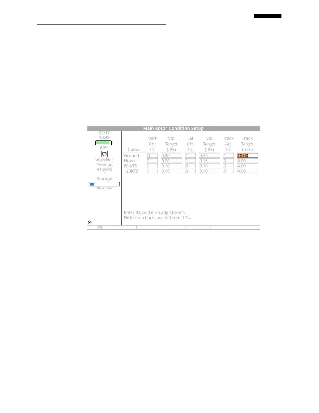
Looking at the example main rotor conditions setup screen above, three charts will be used, two
vertical and one lateral. One tracking influence definition will also need to be created. The first
chart is for vertical measurements at hover only. The second chart is for the averaged vertical
measurements from both FLT 80 and FLT 120. The last chart is for the average lateral
measurement from both Ground and Hover. The tracking influence will use track readings from
Hover measurements. No other measurements will be used to produce corrections for this setup.
Both vertical and lateral vibrations must be 0.20 IPS or greater for the analyzer to present
solutions. Track splits must be 0.25 inches (6.35mm) or greater for the analyzer to present a
solution.
7.1.3.1. – Conditions Setup Screen, Example 2
In the example main rotor condition setup screen above, only one vertical chart ID, one lateral
chart ID, and one tracking adjustment ID have been entered. Based on the ID numbers entered,
all of the vertical measurements for Hover, FLT 80, and FLT 120 will be averaged and the
solution based on this average. The lateral measurement for both Ground and Hover will also be
averaged, with the lateral solution based on this average. Finally, a tracking adjustment based on
the recorded track split on the ground will be presented. This type of setup would be used with a
ship that requires a pitch change link adjustment on ground based on visual track and a trim tab
adjustment based on the vertical vibration in flight.
7.1.3.2. – Conditions Setup Screen, Example 3
 Loading...