Chapter 3. 9500 MXC Nodes
Vol. II-3-20 Alcatel-Lucent
NCC User Interfaces
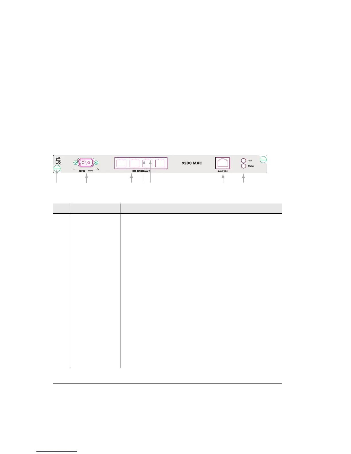
Figure 3-10 shows the NCC front panel layout.
Table 3-7 on page 3-20 describes the front panel interfaces.
User access is also provided on the NCC PCB for:
• A fast acting 25A tubular ceramic fuse, located behind the -48 Vdc connector.
• CompactFlash card on the right side of the PCB.
Figure 3-10. NCC Front Panel Layout
Table 3-7. NCC Front Panel Descriptions
No Item/Label Description
1 Plug-in fastener Finger-grip screw-type fastener and card pull (2).
2 -48 Vdc 2-pin polarized D-series 2W2C power connector with captive screw fasteners.
3 NMS 10/100Base-T The four RJ-45 connectors provide Ethernet network management access. 9500
MXC CT login to these ports requires entry of the IP address for the INU/INUe.
Ports may also used to provide NMS connectivity to co-located 9500 MXC INU/
INUes and other Alcatel-Lucent and third party radios. Ports auto-resolve for
straight or cross-over cables.
4 Ethernet orange LED Orange flashing LED indicates Ethernet receive activity. Off indicates no receive
activity. (Fitted to each RJ-45 NMS connector)
5 Ethernet green LED Green LED indicates connection of an Ethernet link. Off indicates no Ethernet
link connection. (Fitted to each RJ-45 NMS connector)
6 Maint V.24 RJ-45 connector provides a V.24 serial interface option for CT access. Includes
a default IP address, which means knowledge of the INU/INUe IP address is not
required at login.
7 Test LED Provides indications of:
Off INU/INUe power off.
Green Normal operation.
Orange flashing INU/INUe is in a test/diagnostic mode, for example,
loopbacks are set.
1
2
3
45
67