9500 MXC User Manual
3DB 23063 ADAA - Rev 004 July 2007 Vol. II-2-7
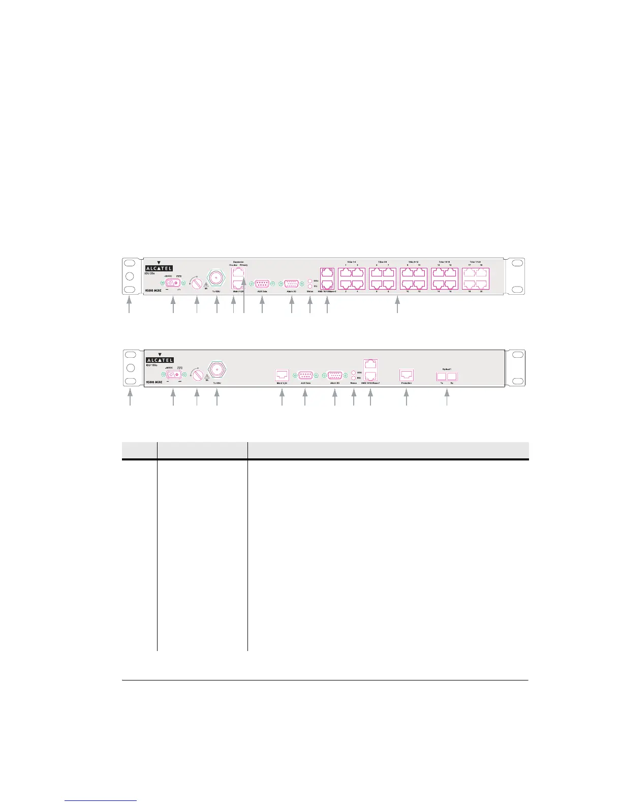
Front Panel Layout
• Figure 2-1 shows the IDU 20x front panel.
• Figure 2-2 shows the IDU 155o front panel.
• Refer to Table 2-4 for names and descriptions of numbered components.
Figure 2-1. IDU 20x Front Panel Layout
Figure 2-2. IDU 155o Front Panel Layout
Table 2-4. Front Panel Layout Description
No Item/Label Description
1 Rack Ear and
Grounding Stud
Rack attachment bracket for the IDU. One ear has a grounding stud for IDU
grounding. The ears can be fitted either side and provide flush-with-rack-front
mounting.
2 -48 Vdc 2-pin D-series 2W2C power connector. Includes screw fasteners.
3 Fuse 5A time-lag fuse and power on/off switch. ON is when the fuse head is in the
vertical position; OFF is when the head is rotated to the horizontal ‘0’ position.
4 To ODU Type N female connector for jumper cable connection to the surge suppressor
located at the cable entry point to the building.
5 Maint V.24 RJ-45 connector provides a V.24 serial interface option for 9500 MXC CT (CT)
connection. It supports a default IP address, which means knowledge of the
Terminal IP address is not required at login.
6 Aux Data DB-9 connector provides one synchronous or asynchronous data service
channel. Selection of synchronous (64 kbps) or asynchronous (max 19.2 kbps)
is via 9500 MXC CT.
1
2
3
4512 6
7
89 13
1
2
3
45
16
126
7
89