9500 MXC User Manual
3DB 23063 ADAA - Rev 004 July 2007 Vol. IV-7-5
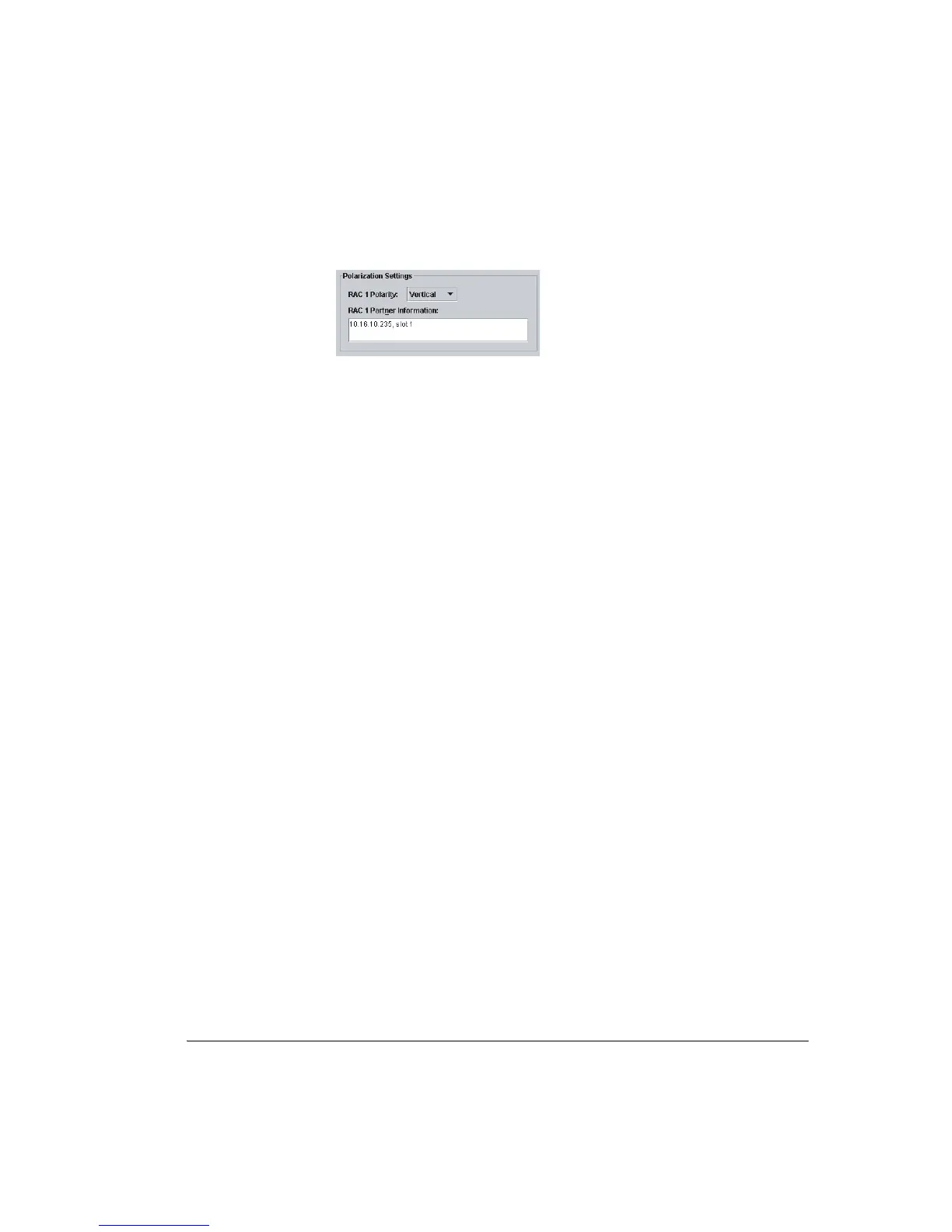
Figure 7-2. Polarization Settings Panel
Co-channel links can be hot-standby or diversity protected. Refer to Figure 7-6
on page 7-17 for an example hot-standby protected screen.
Link/Ring Configuration Procedure
This procedure applies to non-protected, hot-standby, diversity, and ring links.
• A typical Node non-protected plug-ins screen for a 16xE1, 16 QAM
configuration is shown in Figure 7-3 on page 7-6.
• A typical hot standby link plug-ins screen is shown in Figure 7-4 on page 7-15.
Apart from the Protection Setting advice, the same screen is typical of a space
diversity link.
• A typical ring protection plug-ins screen is shown in Figure 7-5 on page 7-16.
Apart from the Protection Setting advice, the same screen is typical of a
frequency diversity link.
• A typical co-channel protected plug-ins screen is shown in Figure 7-6 on
page 7-17.
Additional information on protected operation is provided at:
• Protection Options on page 7-14
• Protection Settings on page 7-18
• Coupler Losses on page 7-19
 Loading...