Chapter 2. 9500 MXC Terminals
Vol. II-2-22 Alcatel-Lucent
IDU ES Layout
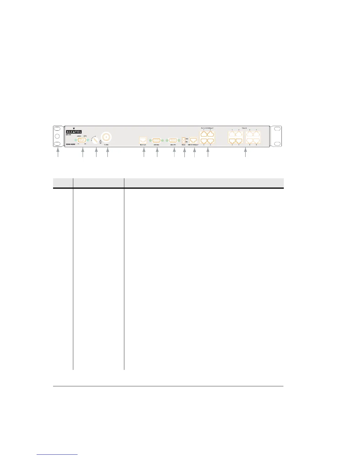
Figure 2-8 illustrates IDU ES front panel layout and interfaces. Refer to
Table 2-10 for a description of numbered items.
Figure 2-8. IDU ES Front Panel Layout
Table 2-10. Front Panel Layout Description
No Item/Label Description
1 Rack Ear and
Grounding Stud
Rack attachment bracket for the IDU. One ear has a grounding stud for IDU
grounding. The ears can be fitted either side and provide flush-with-rack-front
mounting.
2 -48 Vdc 2-pin D-series 2W2C power connector for all IDUs. Includes screw fasteners.
3 Fuse 5A time-lag fuse and power on/off switch. ON is when the fuse head is in the
vertical position; OFF is when the head is rotated to the horizontal ‘0’ position.
4 To ODU Type N female connector for jumper cable connection to the surge suppressor
located at the cable entry point to the building.
5 Maint V.24 RJ-45 connector provides a V.24 serial interface option for 9500 MXC CT. It
supports a default IP address, which means knowledge of the Terminal IP
address is not required at login.
6 Aux Data The DB-9 connector provides one synchronous or asynchronous data service
channel. Selection of synchronous (64 kbps) or asynchronous (max 19.2 kbps)
is via CT.
7 Alarm I/O HD-15 connector provides access to two TTL alarm inputs and four form C
relay outputs. Connections are mapped in CT.
8 ODU ODU Status LED provides indications of:
Off IDU power off
Green Normal operation
Orange flashing Configuration not supported, software/hardware
incompatible, or diagnostic mode selected.
Red Critical alarm (traffic affecting)
1
2
3
456
7
8 9 14 15