9500 MXC User Manual
3DB 23063 ADAA - Rev 004 July 2007 Vol. III-2-11
Flexible waveguides are frequency band specific and are available in two
lengths:
• 600 mm (2 ft) for frequency bands 18 to 38 GHz
• 1000 mm (3.28 ft) for frequency bands 6 to 15 GHz
Both flange ends are identical, and are grooved for a half-thickness gasket, which
is supplied with the waveguide, along with flange mounting bolts.
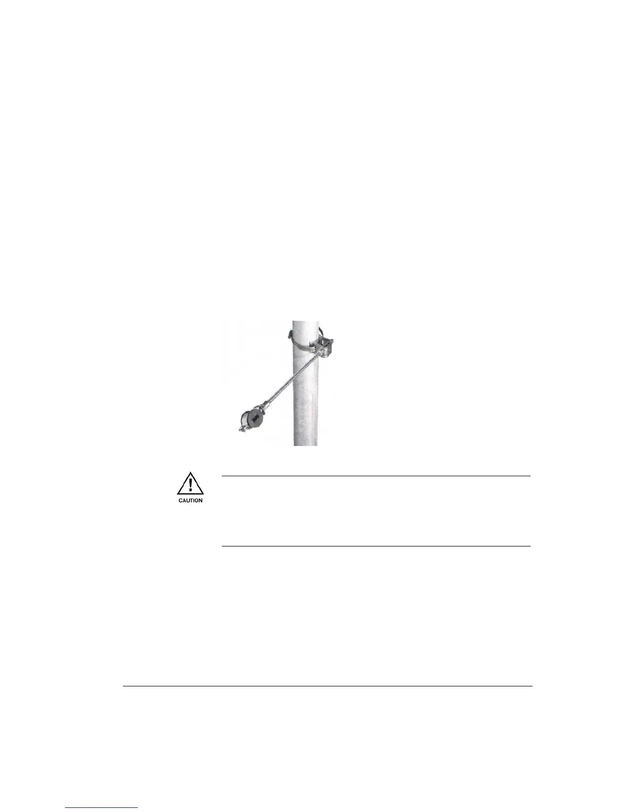
To prevent wind-flex, a flexible waveguide or coax must be suitably fastened or
supported over its length. Where it is not possible to fasten directly to the support
structure, hanger assemblies are recommended, comprising a stainless steel
clamp, threaded rod and a form-fit rubber grommet. Figure 2-10 shows a typical
assembly for a 28 to 38 GHz flexible waveguide.
Figure 2-10. Flexible Waveguide Hanger Assembly
Next steps:
• Waveguide Flange Data
• Remote-Mount Installation Procedure on page 2-12
Waveguide Flange Data
Table 2-1 lists the antenna port flange types used with the ODU 300, plus their
mating flange options and fastening hardware for remote mount installations.
UDR/PDR flanges are rectangular; UBR/PDR flanges are square.
The flexible waveguides have tin-plated brass flanges to minimize
dissimilar-metal corrosion between the aluminum feed-head on the ODU and the
brass antenna port(s) used on most standard antennas.
Where a flexible-waveguide length greater than the standard length in the 9500
MXC accessories list is needed, contact your Alcatel-Lucent service support
center.