Chapter 3. 9500 MXC Nodes
Vol. II-3-70 Alcatel-Lucent
Note: These are maximum values, which require de-rating if the relay is to be
used for frequent-switch applications.
The contact voltage must be restricted to less than 60 Volts for
compliance with SELV regulations.
Maximum current specification applies up to 30 Volts
Alarm Application
Events are mapped to outputs:
• Individual AUX alarm inputs or internal alarm events may be mapped to any
output within the network.
• Multiple input or internal events may be mapped to a common output.
• Mapping is achieved using IP addressing for the destination node, plus a slot
location and output number for the AUX plug-in.
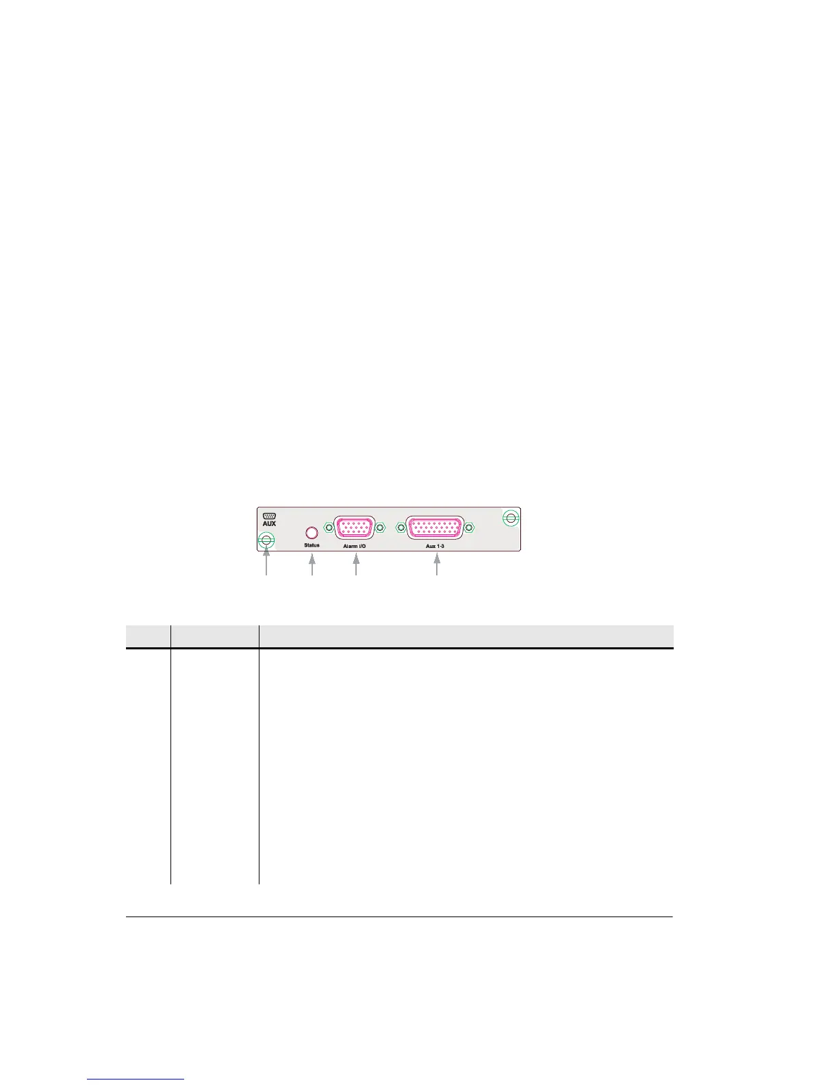
AUX Front Panel
Figure 3-43. AUX Front Panel Layout
Table 3-25. AUX Front Panel Descriptions
12
34
No Item/Label Description
1 Plug-in fastener Finger-grip screw-type fastener and plug-in pull (2).
2 Status LED Status LED provides indications of:
Off INU power off
Green Normal operation
Orange flashing Configuration not supported, or software / hardware
incompatible
1
Red Critical alarm
2
3 Alarm I/O
connector
DSUB 15 connector. Refer to Appendix E for pinout and alarm I/O cable data.
4 Auxiliary
connector
DSUB 26 connector. Refer to Appendix E for pinout and AUX cable data.