9500 MXC User Manual
3DB 23063 ADAA - Rev 004 July 2007 Vol. III-5-3
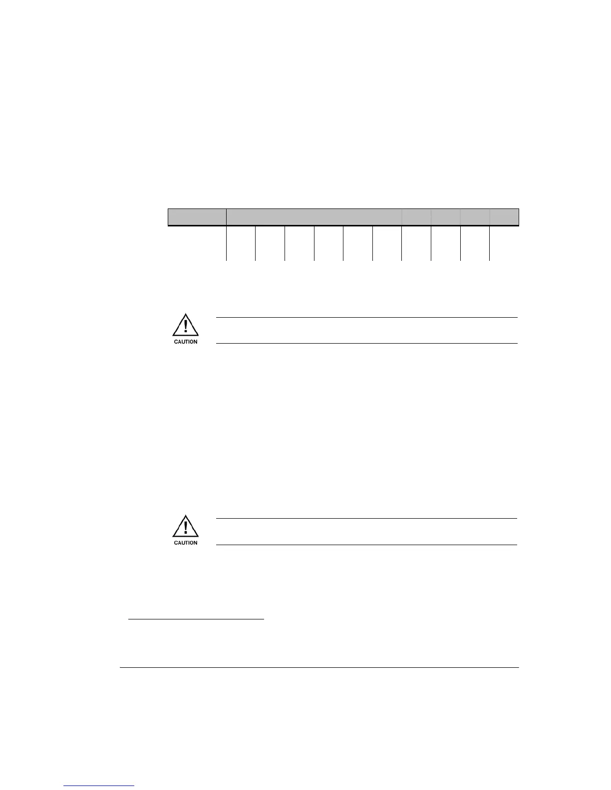
4. Check and record the peak voltage at each end. The RSSI voltage provides a
direct relationship with RSL. An RSSI of 0.25 Vdc { -10 dBm RSL, and each
additional 0.25 Vdc RSSI increase thereafter corresponds to a 10 dBm
decrease in RSL, as follows:
5. Compare actual RSLs to the expected RSLs from the link installation
datapack. Refer to RSL Measurement Guidelines.
6. Replace the BNC weatherproofing cap.
RSL Measurement Guidelines
Interference
The RSSI filter has a nominal 56 MHz bandwidth, which means that depending
on the channel bandwidth used, multiple adjacent channels will be included
within the filter passband
1
. Normally this will not cause a problem as antenna
discrimination (beamwidth) and good frequency planning should exclude
adjacent channel interferers. However at sites where this is not the case, ATPC
should not be enabled.
• ATPC operates on the RSL. Any interferer that affects the RSL will adversely
affect ATPC operation.
• Check for interference by muting the Tx at the far end and checking RSSI/RSL
at the local end.
Units Measurement
BNC (Vdc) 0.25 0.5 0.75 1.0 1.25 1.5 1.75 2.0 2.25 2.5
RSL (dBm) -10 -20 -30 -40 -50 -60 -70 -80 -90 -100
Failure to replace the RSSI BNC weatherproof cap may result in damage to the
ODU.
1
RSSI filter bandwidth is not a function of, nor does it affect receiver adjacent channel C/I performance.
9500 MXC complies with relevant ETSI and FCC co and adjacent channel requirements.
For co-channel XPIC operation and where there is a measurable adjacent
channel RSL, do not use ATPC.