9500 MXC User Manual
3DB 23063 ADAA - Rev 004 July 2007 Vol. IV-2-21
6. Log-in is confirmed by the appearance of the CT System Summary screen.
Refer to System Summary on page 15-2 of Volume IV.
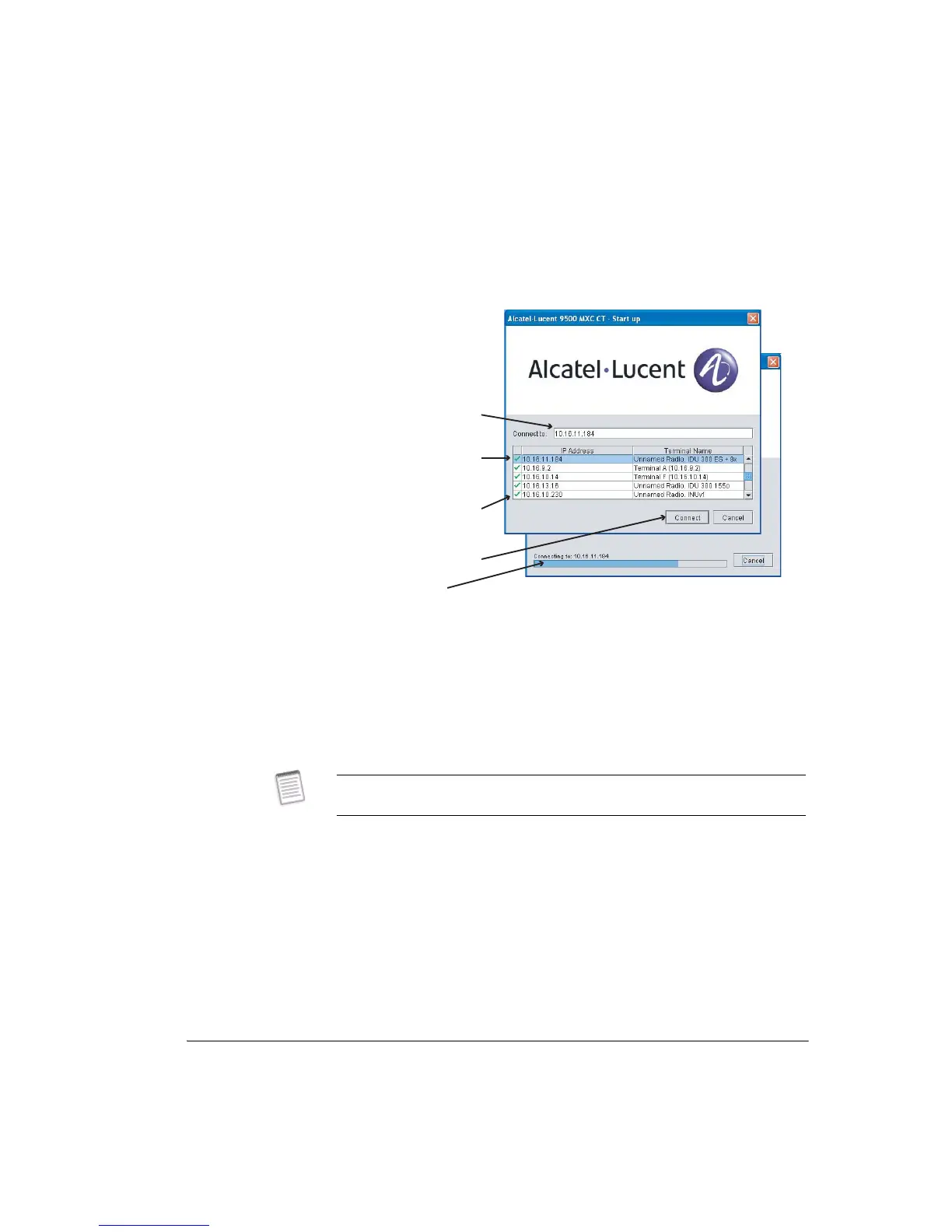
Figure 2-1. 9500 MXC CT Start-up Screen for an Ethernet Connection
Using an Ethernet DHCP Connection
The procedure describes connection where a DHCP server is enabled on the 9500
MXC radio (or radios) to be connected to.
• For radios that are DHCP server enabled the TCP/IP properties window on your
CT PC must be set to obtain an IP address automatically for the DHCP
mechanism to operate. See Setting Up A DHCP Ethernet 9500 MXC CT
Connection on page 2-9.
DHCP Connection
This procedure applies to a 9500 MXC radio that is DHCP server enabled.
1. Ensure your PC is configured to obtain an IP address automatically.
2. Connect your PC to the 9500 MXC 10/100Base-T NMS port of the radio you
wish to connect to.
3. Open the CT start-up screen. Refer to Figure 2-1 on page 2-21.
4. From the list of terminals displayed select the target terminal.
Connection
progress bar
Tick indicates a valid LAN
connection exists between
the CT PC and the
connected terminal
List shows all current LAN
connections and up to 10
previous connections
Click to connect
Current selection
For rules, hints and tips on DHCP server setting and operation, refer to DHCP
Server Function on page 10-13 of Volume IV, Chapter 11.