9500 MXC User Manual
3DB 23063 ADAA - Rev 004 July 2007 Vol. IV-9-3
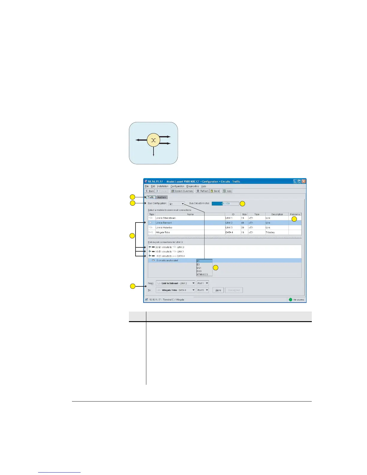
Typical Circuits Configuration Screen
Figure 9-1shows a circuits screen for a typical aggregation node comprising a
40xE1 link interconnecting with a 16xE1 link, a 20xE1 link and a DAC 16x:
Figure 9-1. Typical Circuits Screen
Item Description
1 Tabs provide access to Traffic or Auxiliary circuits configuration.
2 Select the backplane type from the drop-down menu (Item 5).
3 Circuit-configurable modules are listed in the upper window. Click on one to
view its port-to-port connections in the lower window.
Connections are shown in summary form when toggles are in the up position.
The names in the Name fields are those applied to the modules in the System
Summary screen.
16xE1
40xE1
4xE1
9500 MXC Node
20xE1
1
2
3
4
5
6
7