Chapter 3. Installing the INU and INUe
Vol. III-3-2 Alcatel-Lucent
• Power Cable on page 3-3
• Fuses on page 3-3
Front Panel Layout
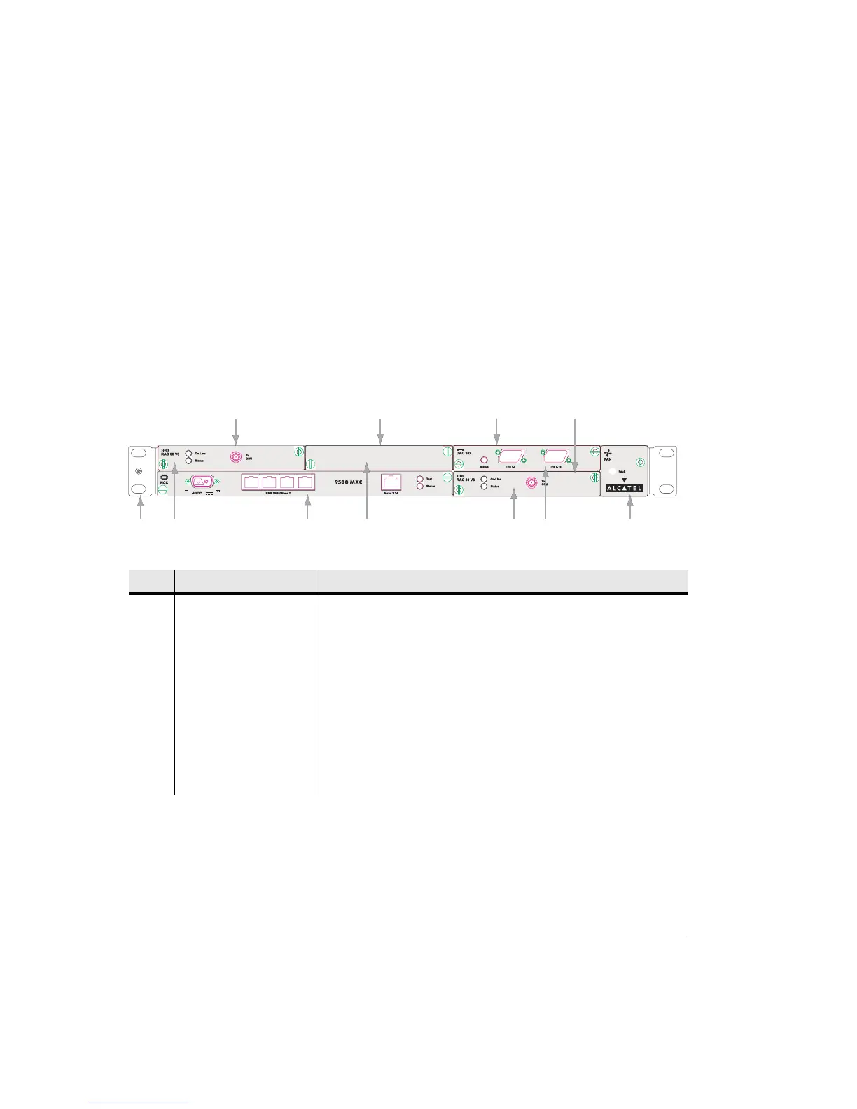
Figure 3-1 shows an example of an INU front panel, with one DAC x16, two
RAC 30s, and a blanking panel over the unused slot. The names and descriptions
for this example are listed in Table 3-1. For a full description of all plug-ins and
their front panel layouts, refer to Plug-in Cards on page 3-15, Volume II,
Chapter 3.
Figure 3-1. Typical INU Front Panel Layout
Table 3-1. INU Front Panel Descriptions
No Item/Label Description
1 Rack Ear and grounding
stud
Rack attachment bracket for the IDC. One ear has a combined ESD and IDC
grounding stud. The ears can be fitted either side, which provide
flush-with-rack-front mounting.
2 RAC 30 RAC 30 fitted in slot 1
3 NCC Mandatory Node Control Card (dedicated slot)
4 Blank Panel Blanking panel fitted to slot 2
5 RAC 30 RAC 30 fitted in slot 4
6 DAC 16x 16xE1/DS1 DAC fitted in slot 3
7 FAN Mandatory fan plug-in (dedicated slot)
Fault
FAN
Fault
FAN
12
45
6
To
ODU
RAC 30
On-Line
Status
To
ODU
RAC 30
On-Line
Status
To
ODU
On-Line
Status
To
ODU
On-Line
Status
Slot 1 Slot 2 Slot 3
Slot 4
37
-48VDC