9500 MXC User Manual
3DB 23063 ADAA - Rev 004 July 2007 Vol. II-3-55
• Payload throughputs are determined by the configured port and channel speeds
(bandwidth), QoS settings, and internal and external VLAN information.
• Ethernet throughputs supported on the two transport channels depend on the
backplane bus setting:
• For a 2 Mbps / E1 or 1.5 Mbps / DS1 backplane the channel capacity
selections support:
• A maximum of 200 Mbps on one channel (C1 or C2), or 200 Mbps total
using both channels.
• Capacity selections are made in multiples of 1.5 Mbps or 2 Mbps.
• For an STM1 backplane the channel capacity selections support:
• 150 Mbps on channel C1 or C2
• 300 Mbps on channel C1 or C2
• 150 Mbps on both C1 and C2
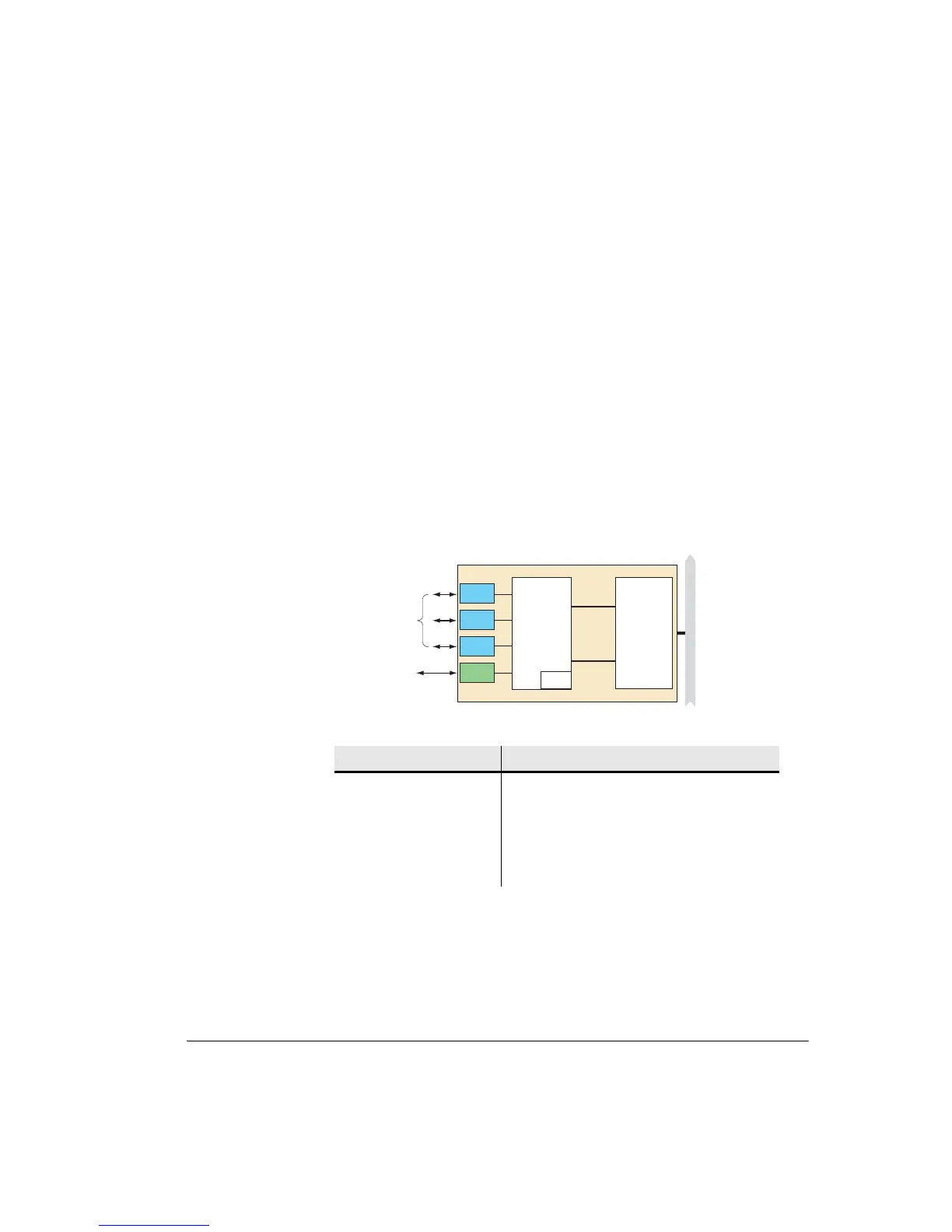
Figure 3-35. DAC GE Block Diagram
Table 3-23. SFP Optical Port Specifications
NOTE: Nominal throughputs in Mbps are generally used. For example a 150
Mbps or 300 Mbps throughput has a measured maximum for a 1518 byte frame
of 152 or 308 Mbps respectively.
Wavelength: 1310 nm
Maximum launch power: -3 dBm
Minimum launch power: -9.5 dBm
Link distance Distances to 10 km / 6 miles with 9/125 µm
optical fiber; 550m / 600 yards with 50/125 µm or
62.5/125 µm fiber
Port 1
Port 4
Port 3
Port 2
Ethernet
Switch
C1
C2
Transport
Channels
FPGA
Bus Interface
RJ-45 Ports
10/100/1000Base-T
uP
Mode
QoS
RSTP
Aggregation
BUS
SFP Optical Port
1000Base-LX