Chapter 3. 9500 MXC Nodes
Vol. II-3-88 Alcatel-Lucent
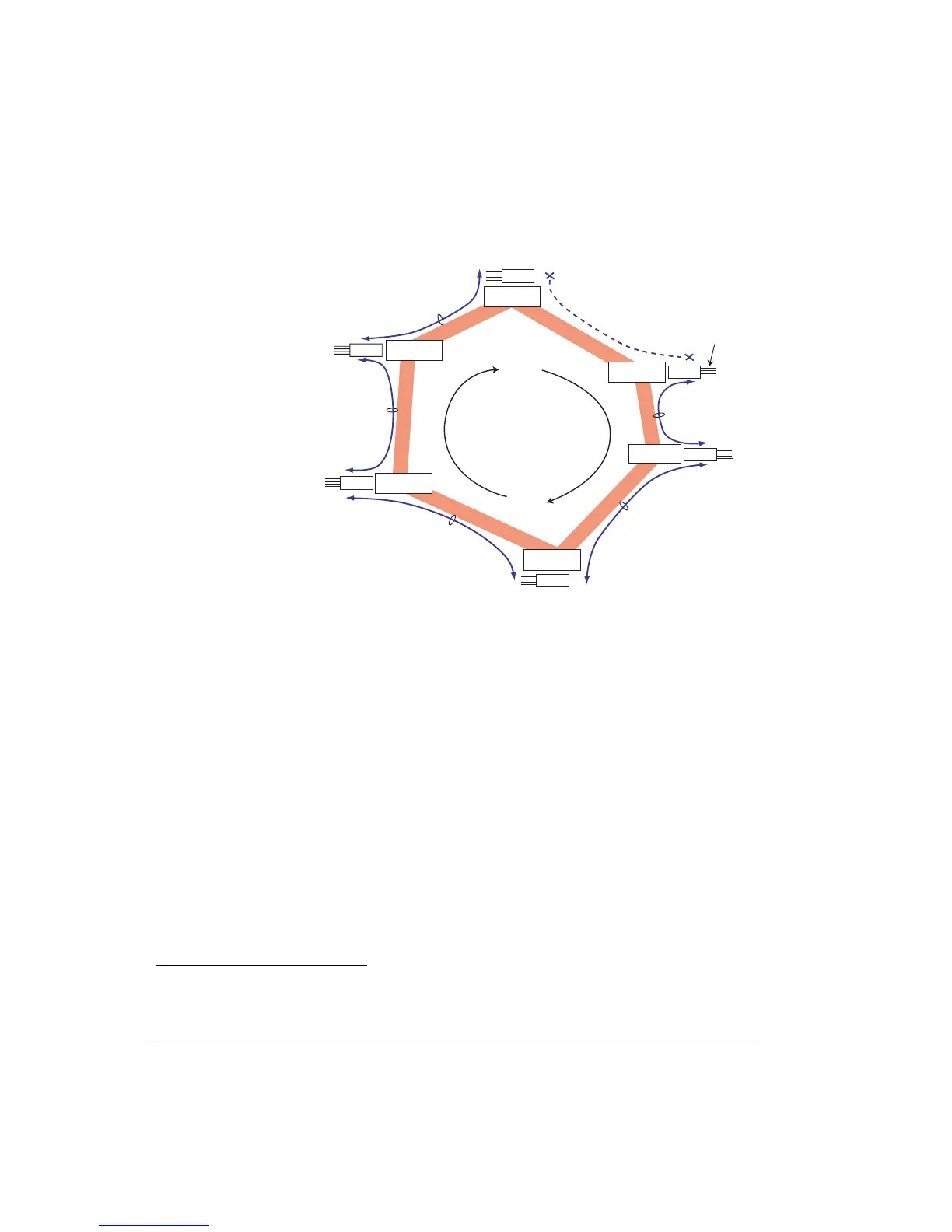
Figure 3-54. Example of Radio-Environment Protection for Ethernet Traffic
When used in this way the DAC ES must be set for transparent mode, and the
transport channels would normally be configured for identical Nx2 Mbps (or
Nx1.5 Mbps) capacity. The example shows each hop on the ring configured for a
6x2 Mbps DAC ES transport channel.
Note that DAC ES Ch 1 on Node A and Ch 2 on Node B are not used, and the
five 6x2 Mbps circuit groupings used are unique to each Ethernet node-node
channel, requiring a total of 30x2 Mbps on the ring.
Ethernet Environment
Ethernet alternate-path ring protection is enabled by the rapid spanning-tree
algorithm held within RSTP switches
10
at each ring site.
The contention that would otherwise occur with the arrival of looped Ethernet
frames is managed by RSTP, which creates a 'tree' that spans all switches in the
ring, forcing redundant paths into a standby, or blocked state. If subsequently one
network segment becomes unreachable because of a device or link failure, the
RSTP algorithm reconfigures the tree to activate the required standby path.
RSTP is defined within IEEE 802.1D-2004 and is an evolution of the Spanning
tree Protocol (STP).
• For DAC ES and IDU ES an external RSTP switch is required.
Node B
Node A
Node C
Node E
Node F
Node D
Ethernet port
connections
6x2 Mbps Transport
on ring ccts 1 to 6
DAC ES
DAC ES
DAC ES
DAC ES
Ch 2
Ch 1
Ch 2
Ch 1
Ch 1
Ch 2
Ch 2
Ch 1
DAC ES
DAC ES
Ch 2
Ch 1
6x2 Mbps Transport Ch
on ring ccts 7 to 12
6x2 Mbps Transport Ch
on ring ccts 25 to 30
6x2 Mbps Transport Ch
on ring ccts 19 to 24
6x2 Mbps Transport Ch
on ring ccts 13 to 18
Protected Nx2 Mbps ring
Ethernet ring must
not be closed
10
Layer 2 switch with a rapid spanning-tree protocol option. A switch need not be located at each site, but
is recommended to avoid the potential for a site to become isolated in the event of a path/link failure.