Chapter 5. Antenna Alignment
Vol. III-5-20 Alcatel-Lucent
Line BB represents the azimuth tracking path with the antenna tilted down
slightly. Signal strength readings show only the first side lobe peaks, 4 and 5. In
some instances the side lobe peaks are unequal due to antenna characteristics,
which can lead to the larger peak being mistaken for the main beam. The correct
method for locating the main beam in this case is to set the azimuth position
midway between the first side lobe peaks, and then adjust the elevation for
maximum signal.
Line CC represents an azimuth tracking path with the antenna tilted down further
still. The first side lobe signal peaks (6 and 7) appear as one peak, leading to a
mistaken interpretation of a main beam. The correct method for locating the main
beam is to set the azimuth at mid peak, between 6 and 7, and then adjust
elevation for maximum signal.
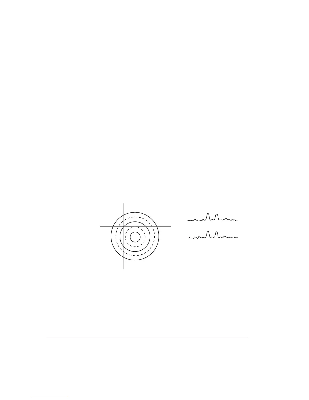
This first side lobe peaking is probably the most frequent cause of misalignment
in both azimuth and elevation, especially so if one side lobe peaks higher than the
other, as shown in Figure 5-5. A common error is to move the antenna left to
right along line DD, or top to bottom along line EE, always ending up with the
maximum signal at position 1.
Figure 5-5. Example Tracking Path Signals Centered on the First Side
Lobe
D
E
E
D
1
2
3
1
1
3
22
Head-on View of Azimuth and Elevation
Tracking Paths Centered on the First Side Lobe
Signal Levels for Each Track
E
D
E
D