9500 MXC User Manual
3DB 23063 ADAA - Rev 004 July 2007 Vol. IV-9-15
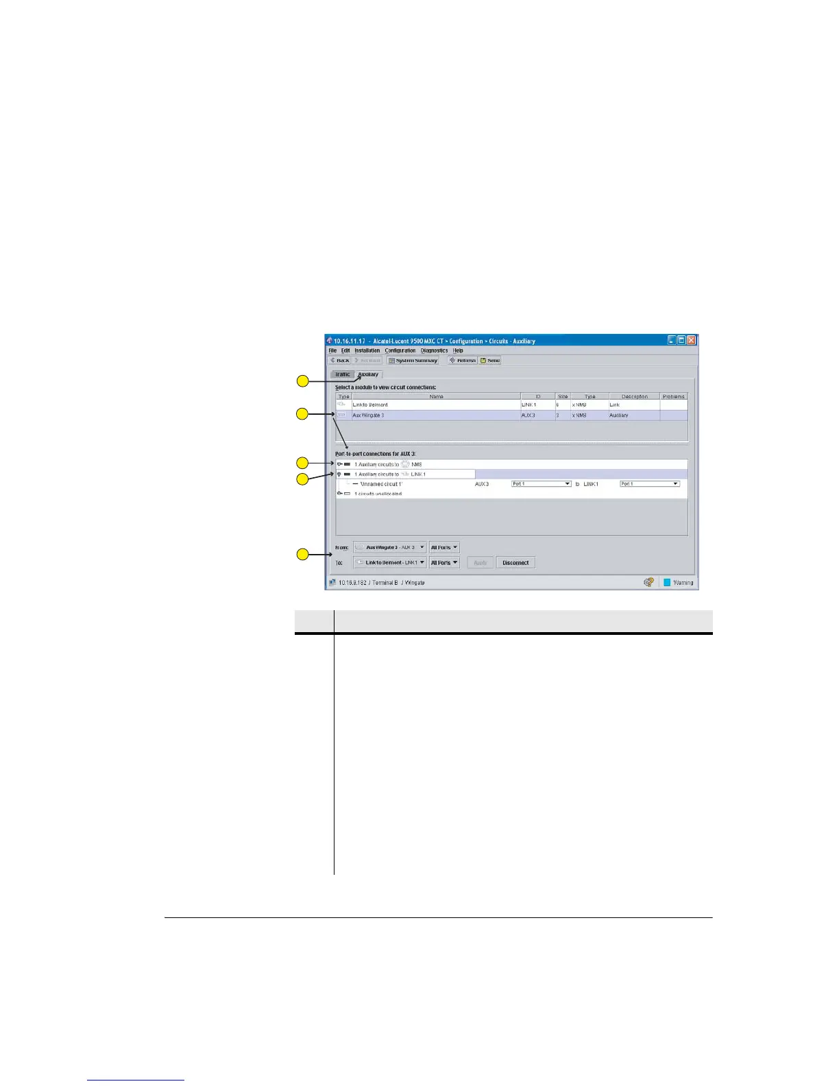
Auxiliary Circuits Screen
Figure 9-8 is an example of an auxiliary screen showing AUX ports 1 and 3
configured for DATA transport, and port 2 configured for NMS.
Only Data circuits can be configured in this screen. NMS ports are shown only to
provide a complete picture of all AUX ports.
Figure 9-8. Auxiliary Circuits Screen
Item Description
1 The Auxiliary circuits tab is selected.
2 The AUX plug-in (AUX in slot 3) is selected (highlighted), which populates the
port-to-port connections box and the From tab.
3 This AUX circuit has been configured for NMS in the AUX plug-ins screen.
No action is required or possible from this screen.
4 This AUX circuit has been configured for data in the AUX Plug-ins screen.
Click the toggle down to view its circuit connections. The example shows one
auxiliary data circuit has been established between AUX 3 and Link 1 using the
Auxiliary circuits screen.
The example also shows the remaining circuit is unallocated; one AUX Plug-in
supports a maximum of three circuits.
5 Auxiliary circuit connection and disconnection action is identical to Traffic
circuit connection and disconnection.
1
2
3
4
5